We have an incredible array of batteries to power our night vision devices yet NO WAY TO RECHARGE THEM, placing a HUGE burden on our logistics system to keep pumping forward fresh batteries placing our truck drivers at risk to enemy ambush on the non-linear battlefield (NLB). The HMMWV 4x4 truck does not have a cigarette lighter outlet and is not ready to be a charging source to renew a fewer collection of batteries to keep units combat effective without depending on resupply which as events in Iraq have shown is stretched to the limit and subject to enemy denial.
The good news is solutions are at hand! 1st Tactical Studies Group (Airborne) Director, Mike Sparks has discovered with other Soldiers several ways to create electrical power self-sufficiency via rechargeable batteries and vehicle, human and solar power regeneration means.
1. Charge using fossil fuel ground vehicles
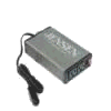
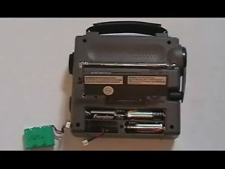
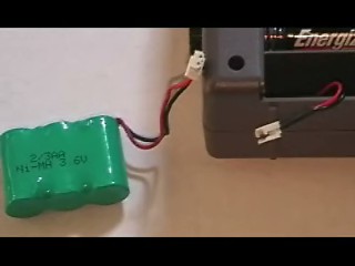
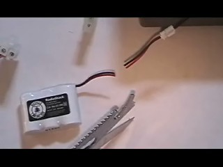
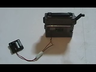
AC power inverters can be purchased from Radio Shack, Best Buy etc, one brand is made by Jensen, and these have alligator clips to attach to the front battery of the HMMWV under the right seat to provide 110 volts while the engine is running. You simply close the seat/battery cover and route the cable and small 4" x 6.4" x 1.9" power inverter to the radio mount right side and cable-tie it in place. There is a quick-disconnect clip on the wire and an on/off power switch that should be turned on only when the engine is running.
PHOTOS!!!


You now have a means to recharge ALL of your combat equipment batteries! There are more powerful inverters with up to 100 watts of power but they must be special ordered and they are not readily available at places like Best Buy. As we find the specific details on these inverters we will post them here. One place to buy them is Northern Tool and Equipment Company. Look on pages 87-88 of their paper catalog.
Northern Tools and Equipment Company www.northerntool.com
Northern Tool and Equipment
2800 Southcross Drive West
Burnsville, Minnesota 55306
Phone: 1-952-894-9510
Fax: 1-952-894-1020
Business Sales (24 hours, 7 days)
Phone: 1-800-556-7885
Fax: 1-952-882-6927
Consumer Sales (24 hours, 7 days)
Phone: 1-800-533-
Charge-on-the-move
You should only run the power inverter when the HMMWV or better yet, M113 Gavin's engine is on or else you may drain your one 12V battery and make it impossible to have the required 24 volts to crank the diesel engine. You should charge-on-the-move when your HMMWV would be engine on anyway. If you must run devices while the HMMWV is not moving, then you'll need to have the engine on, and this will require fuel. You also should have a surge suppressive power strip to protect your expensive devices in event of a power flare up. The battery inverter from Best Buy has a disconnect in the cable running from the battery box--you don't need to undo the alligator clips under the battery floor plate. Actually you don't need to even do this since the inverter has an off/on switch, if not on it won't draw current from the battery. The cable disconnect is just extra "insurance" in case the switch is bumped on etc.
Our battery expert tells me that the solar trickle chargers you see on HMMWVs, Bradleys, M113 Gavins etc. are just good enough to keep "topping" off the vehicle's batteries for starting but not enough to take dead infantry device batteries and charging them back to life.
This revelation is a HUGE breakthrough akin to the GPS revolution and every Army unit should go out with unit funds and buy these inverters and fit them to their HMMWVS A-S-A-P.
300w power inverter $69.99 + tax from Best Buy:
Jensen
Recotan Accessories Inc
2950 Lake Emma Road
Lake Mary, FL 32746
www.jensen.com
What do you do next?
Let's say you have 25 Soldiers each with an AN/PVS-7B Night Vision Goggle (NVG) using 2 x AA batteries. This means a total of 50 batteries to operate all these NVGs. To have a set of AA batteries charging you need another 50; for a total of 100 rechargeable batteries.
Ni-Cad (NiCAD) rechargeable batteries are notorious for "memory" and low-power problems. Today's Nickel Metal Hydride (NiMH) batteries solve this. The situation can be viewed as follows:
Least Power------------------------------------Most Power
NiCAD-------Alkaline-------NiMH------Lithium
Curently there are no Lithium-ion AA rechargeable batteries available though these exist for cameras. NiMH batteries are superior to disposible alkaline batteries and can be used to give units SELF-SUFFICIENCY from battery resupply woes, reducing the need for ground resupply columns easily ambushed by the enemy. NiMH AA batteries are 4 for $14 at Best Buy or roughly $3.60 each.
Each power inverter has two AC power outlets; without a power strip/surge suppressor this means two AA chargers of 4 batteries each for a total of 8 batteries charging per power inverter. However with 1-2 power surge/outlets you can expand the number of chargers that can be going at one time to 5-10; this means 20-40 batteries could be charging using just 1 power inverter on a HMMWV. Thus, with 3 HMMWVs with 3 power inverters and 6 power surge/strips you can charge at one time 60-120 batteries at one time. Determine the number of HMMWV trucks you have available for battery charging duties and see how many you can have charging simultaneously and go from there.
2. Charge batteries using human power!
You might ask, "What if we don't have a M113 Gavin or a Humvee as a power source?
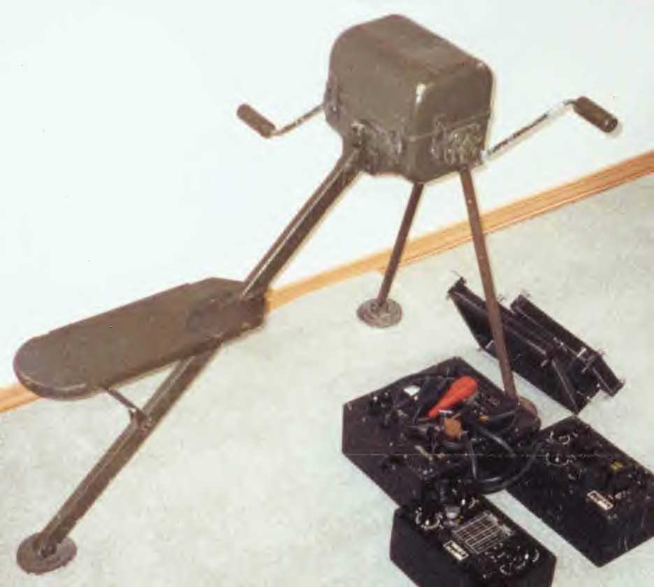
Charge the batteries yourself using human power through a pedal generator or "PEDGEN" or a small handcrank "HANDGEN" set. We used to do this all the time in WW2 (see the John Wayne downed aircraft survival movie "Island in the sky"), and our "Special" Forces have done it for decades with the GN-58 which has now been replaced by a newer generator G-67 generator part of the OP-177/U kit but since its "secret squirrel" stuff, the SF community for years will not share ordering information to get these hand crank generators with us "unwasheds". Thanks to the www we now know the details of these $6, 000 generators that weigh 6.5 pounds and are no longer in production, though we know who makes them now. Army is tinkering around with a tape measure sized "Palm Power" crank generator of dubious capability which you can read via PDF file below:
www.asc2004.com/Manuscripts/sessionH/HP-03.pdf
Or in our "NOTES" section on the bottom of this web page.
www.militaryradio.com/spyradio/rs1.html
OP-177/U Kit
www.frezzi.com/general_1.htm&e=42
General Research Laboratories
Military Support Group
OP-177/U Elements
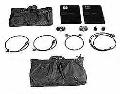
The OP-177/U system kit integrates charging and monitoring of all Communication batteries in the U.S. Special Operations Forces inventory. Batteries may be charged in all environmental conditions with the AC/DC Power Converter, Solar Panel Charger or Hand Cranked generator.
Solar Panel Assembly. These panels can be used in one, two, and four panel configurations to charge 12 and 24 volt batteries through the Power Supply Adapter. Supports recharging of BB590/U, BB490/U, BB588/U and BB542/U.
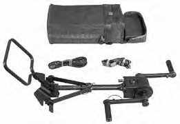
Generator Assembly G-67B/G. A hand cranked generator of advanced design able to provide energy to recharge through a Power Supply Adapter BB590/U and BB490/U batteries. Can directly charge the BB542/U.
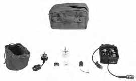
AC to DC Power Converter Kit. The AC-DC converter is a selectable battery charger adaptable with the International Wall Socket Kit to receive world wide AC power. Charges 12, 13, 24 Volt NiCd and 12 and 24 Volt lead acid SOF batteries utilizing the Power Supply Adapter.
Request a Free copy of the 2004/05 Frezzi Catalog here.
Frezzi Energy Systems
Division of Frezzolini Electronics Inc.
5 Valley Street Hawthorne, NJ 07506, USA
Tel: (973) 427-1160
Fax: (973) 427-0934
(800) 345-1030
Business Hours 8:00am to 5:00pm EST
E-mail frezzi@frezzi.com
Send mail to frezzi@frezzi.com with questions or comments about this web site. Copyright (c) 1995 - 2004 Frezzolini Electronics Inc. Last modified: September 01, 2005 [Home]
However, the ENTIRE U.S. military needs human-powered electrical generators in the most efficient high-tech forms possible so we can reduce the resupply convoys that the enemy is ambushing on the non-linear battlefield. Power self-sufficiency must be a FORCE-WIDE CAPABILITY not just for the secret squirrels. All the many batteries an Army unit has CAN be recharged with NO PETROL FUEL WHATSOEVER: via a combination of solar panels, 12v deep-cycle batteries and peda-generator exercise and tactical military All Terrain Bikes (ATBs). PEDGENs can recharge ALL flashlight, night vision device and laptop computer batteries, DVDs etc. Options include David Butcher's recumbent exercise bike, attaching a folding military mountain bike to a Windstream generator stand or their very small hand or pedal crank unit.
HANDGENS
Powerworks

www.powerworksinc.net
Power Works is developing and marketing products that convert human-supplied mechanical energy into electricity, without requiring access to any other external source of power. Products based on our patented technology can be used to recharge batteries that power other appliances (e.g., lights, radios, televisions, water purifiers), without needing to "plug-in" to grid-based electricity, a diesel generator, or an automobile cigarette lighter socket.
Our product designs have the following attributes:
• No requirement for any electrical outlet or fuel input
• Light weight and compact size for ease of portability
• Simplicity and ease of operation, for use by any able-bodied person
• No operating or maintenance costs, no parts to replace
• Simple and quiet to operate
• Watertight and extreme durability, for 100% reliable use under all conditions
• Quiet operation, no emissions or heat produced
As depicted below, Power Works has developed a product prototype that: • Generates 10-15 watts from hand-cranked rotation, with increasing output at higher rotation speeds
• Requires only a modest level of human input effort
• Produces a 13.8 volt DC output, enabling the user to recharge 12 volt batteries commonly employed to supply power to appliances used throughout the world
• Weighs 4 kg (less than 9 pounds), and is of the approximate size of a shoe box, with a hand grip and folding hand-crank for maximum portability
• Can be placed for use either on a raised surface (e.g., table) or the floor/ground
This product was designed primarily for government agencies and non-governmental organizations (NGOs) that are engaged in international efforts to provide:
• Villages without electrification a means to power electrically operated devices that support basic human needs, such as lighting, clean water, refrigeration and communications
• Temporary energy supplies to areas that have been adversely affected by disasters, in support of relief efforts to ensure that basic human needs continue to be met
In addition, this product is also well-suited for certain military, industrial, emergency and recreational purposes worldwide.
Power Works seeks to enter into discussions with parties that are interested in a product of this type, which we believe addresses a substantial worldwide market better than any other available alternative. Please contact us to obtain a specification sheet and to learn more about this product.
Additionally, Power Works continues to identify other markets that would benefit from our technology, in order to develop superior products optimally suited for these markets.
If you have needs for portable human-powered electronic devices, please contact Power Works. Our team is eager to work with you in developing and providing you a product that will meet your exact requirements.
For further information on Power Works, please contact:
Richard Stuebi
President
Power Works, Inc.
c/o NextWave Energy, Inc.
1600 Broadway, Suite 2400
Denver , CO 80202
(303) 352-0377
(303) 573-1830 fax
stuebi@powerworksinc.net
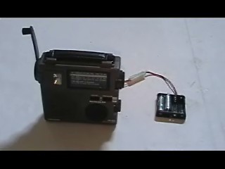
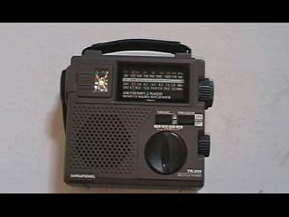
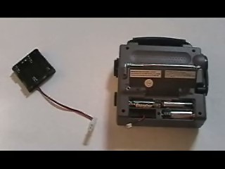
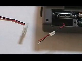
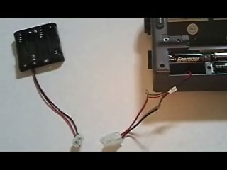
Expedient Battery Charge Solution: Grundig Hand-Crank Radio interface with Batteries America Battery Charge Trays
VIDEO MOVIE OF THE STEPS:
www.youtube.com/v/j04WMo1kPto
STILL PHOTOS OF STEPS:
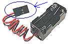
STEP 1 Get a Grundig hand-crank radio
STEP 2 Get Battery Trays with Quick-Disconnect Clips from Batteries America in Middleton, Wisconsin
They have "AA", "C", and "D" Charger trays!
www.batteriesamerica.com/universal_charger_plus!.htm
Part # 4AAT - 4-cell AA charging tray $ 4.50 ea
Part # 4CT - 4-cell "C" charging tray $ 5.95 ea
Part # 4DT - 4-cell "D" charging tray $ 5.95 ea
Batteries America
2211-D Parview Road
Middleton, Wisconsin 53562
CALL TOLL FREE TO ORDER: (800)308-4805
Fax: (608) 831-1082
Inquiries / Technical: (608) 831-3443
Typical office hours for telephone inquiries/orders: M - F, 8:00am to 5:00pm, CST.
Place your order via e-mail anytime at ehyost@chorus.net
For mail or Fax orders, please click on "Order Form" above and print out the handy form.
For some strange reason Batteries America doesn't offer an "AAA" battery tray with quick-disconnect so you'll have to create one from Servocity tray by splicing a quick-disconnector MALE end clip to it:
www.servocity.com/html/battery_trays.html
AAA Battery Tray (4-cell)
Price: $1.95
Part: #54402
Stock: In-stock
Qty:
(620) 221-0421
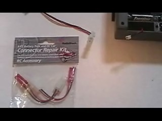
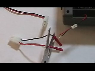
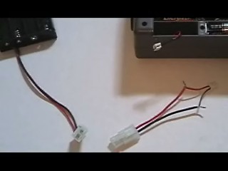
STEP 3 Get a Radio Shack RC repair kit for MALE/FEMALE quick disconnect wires

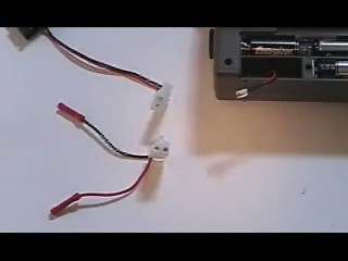

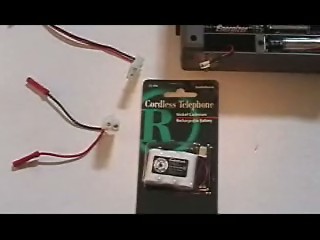
STEP 4 Get an extra 3.6v phone battery for its small white clip
The reason the small clip is retained is if you switched the 3.6 volt phone battery to a large quick-disconnect clip it wouldn't all fit inside the Grundig radio battery compartment during normal radio operation.
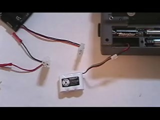
STEP 5 Make the Adapter for the Grundig to interface with the battery trays
Cut extra battery wires, strip and join with FEMALE quick-disconnect wire piece to make an adapter for battery trays for charging

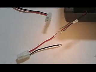

STEP 6 Cut small hole in battery cover for wires to stick out when battery charging
The "pig-tail" only sticks out when you have a battery tray and batteries to charge.
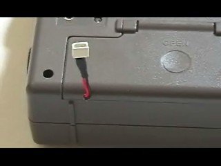
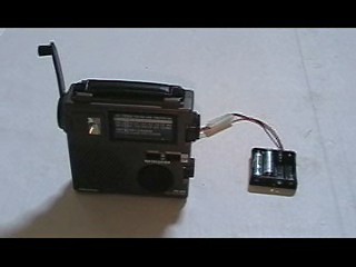
STEP 7: VOILA! you have a battery recharge capability!

Obviously if someone offered the adapter you wouldn't need to make one...how much would it cost, a few pennies?
PEDGENS:
Windstream Power Systems: Human Power Generator

The Human Power Generator is small, portable, and dependable - perfect for emergencies, power failures, remote locations, and off-grid applications. It can be pedaled or cranked by hand to charge 12 volt batteries and run small appliances. Incorporate it into your existing 12 volt system or simply plug your 120 volt appliance into the Portable Power Pack outlet and start pedaling.
The typical average continuous power that can be generated by pedaling the Human Power Generator is up to about 125 watts. The maximum power obtainable through hand cranking typically is about 50 watts. The pedals and optional hand-cranks are interchangeable.
The MkIII Human Power Generator has a durable powder coated steel frame, large rubber feet, and vibration isolated generator. Reengineered for more strength, easier adjustment, and smooth operation, the new MkIII Human Power Generator is the tool for energy education and self-reliant electrical production.
The Human Power Combo comes with the Mk III Human Power Generator (pictured at left) and a stand-alone Portable Power Pack which includes: storage battery, 200 watt inverter (with 300 watt peak power), LED battery voltage readout, connection cables, and a 120 volt outlet to turn your calories into useful power. All you need to do is plug into the Portable Power Pack outlet with your standard AC or DC lights or appliances. To keep your system charged, you just hook up the Human Power Generator to the Portable Power Pack, and pedal or crank by hand...it's the same way you would recharge an ordinary battery, except you provide all the power!
Though even the Tour de France winner (Lance) could not run an entire household's electrical appliances with it, the Human Power Generator System can give you a boost when and where you need it most (charge your car or boat battery, recharge portable electric tool batteries, run emergency back-up lighting, run your PC at your remote cabin). You can maximize the use of your Human Power Generator System by retrofitting your cabin with compact fluorescent lighting and energy efficient appliances.
Stock No. 454213, Mk III Human Power Generator $497 Order Now
SAVE! Stock No. 454217, Human Power Combo (with Portable Power Pack) $850 Order Now
Stock No. 341213, Set of Hand Cranks $25 Order Now
www.windstreampower.com/humanpower/ppg.html
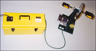
Windstream Power Systems: Bike Power
If you are a cyclist, you know the value of winter training. But do you know the value of your exertion? Your energy is being turned into heat by your trainer. Recapture your energy! The Bike Power generator is the answer for making more power, faster. Attach your bicycle using our tool-free stand and start generating. Pedal to charge 12 volt batteries and run small appliances. Incorporate it into your existing 12 or 24 volt system or simply plug your 120 volt appliance into the Portable Power Pack outlet and start pedaling.
If you already have a trainer or want to build your own stand, the Bike Power Module consists of only the generator, bearings, and friction wheel all conveniently mounted on a steel bracket.
Look for 100 to 300 watts from the Bike Power generator. Just remember that all the energy that you are generating is coming from you; be prepared to give.
The Bike Power generator comes with adjustable folding stand. Place your bike in the stand and secure it with the mounting knobs, adjust the friction wheel with a tool-free knob, and pedal. You'll have DC power ready to charge a battery or power DC loads.
The Bike Power Combo comes with a Bike Power generator and a stand-alone Portable Power Pack which includes: storage battery, 200 watt inverter (300 watt peak power!), LED battery voltage readout, connection cables, and a 120 volt outlet to turn your calories into household current. All you need to do is plug into the Portable Power Pack outlet with your standard AC or DC lights or appliances. To recharge, just hook up your Bike Power to the Portable Power Pack, and pedal...it's the same way you would charge an ordinary battery, except you provide all the power!
Save $$$ with a COMBO!
Stock No. 454104, Bike Power Module $450 Order Now
Stock No. 454105, Bike Power generator $558 Order Now
SAVE! Stock No. 454116, Bike Power Combo (with Portable Power Pack) $899 Order Now
www.windstreampower.com/humanpower/ppack.html
Windstream Power Systems: Portable Power Pack
When you want to extend the use of your Human Power or Bike Power generator beyond direct current, you need a Portable Power Pack. To operate standard 120 volt AC lights and appliances, plug directly into the outlet on the Portable Power System. If you use the Human Power Generator without the Portable Power System, 12 volt DC lights and appliances can be connected to the HPG output or to a small battery (for stabilization).
The Portable Power Pack includes storage battery, 300 watt inverter (with 800 watt peak power), LED battery voltage readout, connection cables, and a 120 volt AC outlet to turn your calories into convient easy to use power. All you need to do is plug your standard AC lights or appliances into the Portable Power Pack outlet. There are even separate DC outputs. To keep your system charged, simply connect a Human Power Generator or Bike Power generator to the Portable Power Pack, and pedal...it's the same way you would recharge an ordinary battery, except you provide the power!
Now the Portable Power Pack does even more with wind, solar, PV inputs. A Windstream or AIR wind turbine and a solar panel can now be connected along side a Human Power Generator to pack even more power into your Power Pack.
LOWER PRICE!! Stock No. 454219, Portable Power Pack $397 (was $425) Order Now
SAVE!! Stock No. 454217, Human Power Combo (with Portable Power Pack) $850 Order Now
SAVE!! Stock No. 454116, Bike Power Combo (with Portable Power Pack) $899 Order Now
Windstream Power Systems Incorporated
PO Box 1604
Burlington VT 05402-1604 USA
Tel (802) 658-0075 Fax -1098
email: info@windstreampower.com
Israelis: Rechargeable Batteries for Military Use
Notice the mention of hand-crank recharging....great IF YOU HAVE ONE!
www.defense-update.com/features/du-1-04/battery-rechargeable.htm
Year 2004 Issue: 1 Site Map
In a network centric environment, where communications (and transmission) of data at high capacity are required, power requirements for portable and mobile electronics is outgrowing existing power sources capacity, leading to a shorter service per battery. Therefore, using regenerable power is becoming critical for military planning.
The use of rechargeable technology has many benefits for military users, especially in cost saving and logistics. However, rechargeable Ni-Cd batteries have high specific weight, low energy density (NiMH) and limited capability in low or high temperatures, when compared to primary technology, and therefore, were used mainly for training. Recent technologies made significant improvements in energy density and reduction of total cell weight, especially with the introduction of lithium-ion and Lithium ion polymer rechargeable technologies.
The British Army is currently fielding a new range of rechargeable power sources for its Bowman battlefield communications system, the next generation communications system for the UK military. The new Lithium Ion batteries will replace Ni-Cd cells used in the current Clansman systems. The new batteries will power portable radios, handheld computers, Global Positioning Systems and encryption devices. The U.S. Army is also moving some units to use rechargeable batteries. For example, Units in Afghanistan are now using only rechargeable batteries such as BB 2590.
The British Army is currently fielding a new range of rechargeable Li-ion batteries, replacing older and heavier Ni-Cd cells. The lightweight batteries offer much improved operation in extreme temperatures, with a range of -51C to +75C degrees. The temperature performance of the Cell will end the practice of "shirt stuffing" whereby the existing Ni-Cd battery is carried next to the skin in an attempt to keep it warm. Extended operational life and lower weight also improve the Soldier's load factor. A typical 6 man patrol will have full control over its battery resources, and be able reduce its attributable battery weight load from 14kg to less than 3kg - giving advantages in both mobility and capacity for other equipment.
When properly implemented, self-charging of batteries enable re-use of inventory and reduced burden on the supply channels. In the absence of electric power, charging can be done through solar power, windmills and hand-crank Generators and fuel cells. Future recharging technologies are also in development, utilizing photo-voltaic and kinetic power sources.
SOLAR: What are the Natick milicrats up to these days on power solutions? What can we do Commercial, Off-The-Shelf? (COTS) How about Solar-Powered M113 Gavin Light Tanks!

www.youtube.com/watch?v=RbWbkOkTydk
Its entirely feasible now to have light tanks like the M113 Gavin powered completely by electric drives; Li-ion batteries can store power to drive the light tank/APC for 50 miles in extreme silent "stealth" mode; or power sensors all night without fear of not being able to crank the diesel/JP-8 engine in the morning to recharge. In fact, COTS solar panels are available that can be arrayed on the outside of the Gavin so THE TANK'S BATTERIES CAN BE RECHARGED BY SOLAR POWER WITHIN A FEW HOURS. So even in a war emergency without fossil fuels, light tanks can at least operate for short distances. The same thing applies to military electric mountain bikes (eMTBs) that can operate from the M113 Gavin "mother ship".
Self-sufficient Forward Operating Bases (FOBs) and Forward Operating Locations (FOLs)
The number of solar panels a tank can carry is limited but as PV technology improves, the number needed to recharge will decrease. However, for an ISO shipping container "BATTLEBOX"; we can easily fit enough solar panels on the roof to POWER THE ENTIRE BATTLEBOX WITH EVEN AIR CONDITIONING!
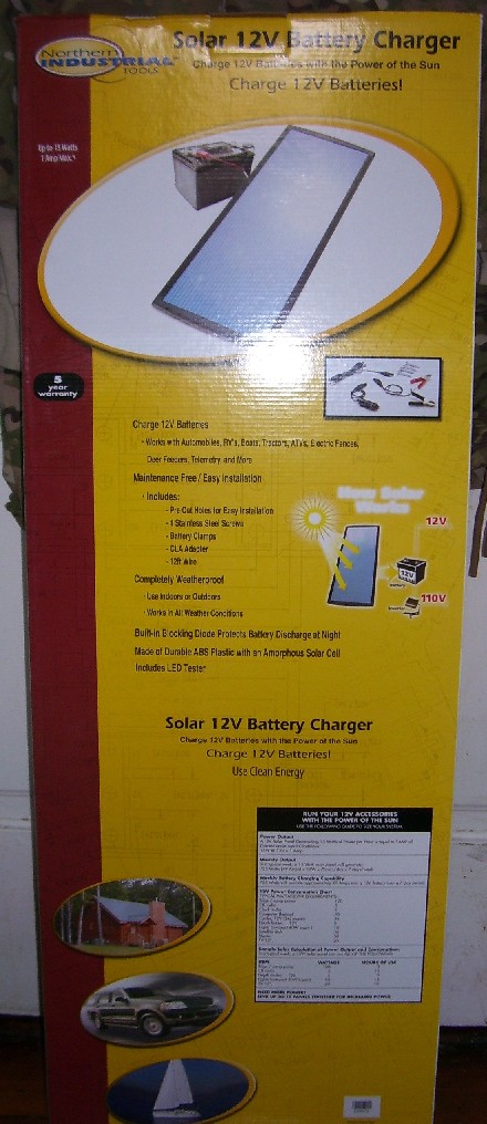
Northern Tool & Equipment offers a 15-watt solar panel for $100 that is very effective in a small 1 foot be 3 foot space....

The Wind Chaser A/C unit above only needs 690 watts of power to operate! Even with 15-watt solar panels this amount can be collected!

www.ravendesigns.net/Default.aspx?tabid=28
FIELD MAN-PORTABLE SOLAR BATTERY RECHARGERThe field portable Solar Battery Recharger (SBR) by Raven Designs is a significant step forward in battlefield power supply. Utilizing the Pure Power renewable resource current generator technology, developed by Atira Technologies and the Naval Post Graduate School in Monterey, California, substantial, useable, renewable power is available in the field.
The Pure Power technology, which can be described as a current generator with power point tracking, is a small, lightweight electronic device which is able to utilize any available light energy and convert it into a useable current to either charge any voltage battery, or directly run equipment in the field. The key with this technology is that it is capable of transforming any useable light energy, including shaded light and artificial light sources. Even when the solar panels are partially to fully shaded, current to recharge a battery is generated. To our knowledge, no other technology in the world is capable of achieving these results. What this means for the Warfighter is that even in less than ideal solar conditions (shaded, camouflaged, clouded, etc.), batteries will be able to be recharged on the battlefield.
Field testing has been conducted under various environmental conditions: A field test conducted in Kodiak, Alaska (latitude 57'45'N), in the month of November, with a very low sun angle, temperatures in the 30's, 3.5 hours of tree shaded exposure and 4.5 hours of direct sun, gave a 26% recharge to a completely drained Ultralife UBI-2590 battery (the BA-5590 rechargeable replacement). A test in Monterey, California (latitude 36'36'N) during the last week of November with the SBR at a 45 degree angle to the ground (roughly 90 degrees to the sun) and never moved to track the sun, recharged the same battery by 71% in 8 hours. The next day, also with clear skies, the SBR was hung from a tree (vertical to the ground), rotated once during the day to track the sun, and recharged the UBI-2590 battery in 8 hours. Testing in ideal conditions (summer sun, and the unit periodically rotated to roughly follow the sun) at mid latitudes, shows 100% UBI-2590 battery recharging in less than 7 hours. These different testing conditions, from the low angle, partly shaded sun, to direct, full sun, illustrates the viability of this technology.
When coupled with the field versatility of the Solar Battery Recharger by Raven Designs, the Warfighter is presented with a real world solution to many battlefield power supply problems. By reducing the weight and bulk of the required battery supply of today's Warfighter, individuals and units can move more quickly, safely, and with more endurance. By being able to recharge batteries in the field, mission durations can be safely lengthened.
Able to recharge any voltage of battery, the SBR consists of two elements. First is the solar panel unit itself, comprised of 10 flexible solar panels sewn onto a coated nylon tarp, which can be laid out flat on the ground or over a vehicle, hung from a tree or pole, or can be securely attached to a backpack to generate power while ground troops are moving during the day. The panel can be buttoned up to adjust for different sized backpacks. The second SBR element is the battery recharger attachment. This unit is configured to fit directly on the Ultralife UBI-2590 rechargeable 15/30 V battery (rechargeable BA-5590 military battery). All power generated by the solar panels will be dumped directly into the UBI-2590, which can be used as is, or can then be utilized to recharge other batteries. The SBR recharger attachment is equipped to recharge AAA, AA and D batteries directly, and also has bare wire clips, 24V DC, and 110V AC interfaces for maximum battlefield versatility.
Below, Natick makes the case for lightening the Soldier's load via rechargable batteries to sell his solar power cells. It doesn't do much for a Soldier on the move but back at his Forward Operating Base camp if he has ISO container BattleBoxes, he has surface area on the roof for solar cells that can be adequately camouflaged.
However, human power generation should be the primary way to recharge batteries for self-sufficient BattleBoxes since it can be taken with you and doesn't need sunlight to work. Fossil fuel powered TAFVs like the M113 Gavin when moving should be recharging batteries as we discussed before.
www.rdecom.army.mil/rdemagazine/200412/itl_photovoltaics.html
RDECOM Magazine | in the lab | TITLEPhotovoltaics Shine Into New Territory
U.S. Army Soldier Systems CenterNATICK, Mass. -- Sunlight is the bright filling station above that never asks for money or runs out of fuel for photovoltaic products, and some scientists believe that the sky is the limit for a new generation of photovoltaic technologies in development at the U.S. Army Soldier Systems Center here.
A promising technology that's existed for decades, photovoltaic (PV) solar cells convert light energy into electricity without noise, moving parts, fuel consumption or pollutant emissions. A breakthrough arrived in the past five years when PV technology transformed from the traditional large, heavy, rigid, reflective and expensive glass panels into lightweight, conformal and inexpensive devices that now can be directly integrated into textiles and warfighter systems, according to Lynne Samuelson, a research chemist in the Science and Technology Directorate.
"There's a lot of room to grow on how power is harvested according to the ambient light," Samuelson said. "Already it's at a usable level."
It's seen as boon to the military for a variety of reasons. Warfighters could cut their battery load weight in half when PV cells are used in combination with rechargeable batteries to power individual items such as night vision goggles, according to Steven Tucker, an electrical engineer in the Collective Protection Directorate.
"On 72-hour and longer missions, it makes a lot more sense to carry rechargeable batteries," Tucker said. "You get rid of that logistics tail by minimizing re-supply with disposable batteries. The benefit/weight payback for a photovoltaic charger and rechargeable battery combination is incredibly quick, and out past 72 hours it just keeps getting better."
Less weight means better mobility, and the ability to recharge batteries on-the-move can increase sustainability, extend mission times and distance from tactical operations centers, and reduce logistics support requirements.
Replacing or decreasing the number of liquid-fuel-powered generators further reduces logistics, and lowers the heat and sound signature in the field for improved stealth. It's also a potential lifesaver as an emergency back-up power in case generators fail, say, in a field hospital.
These benefits are possible because of new lightweight and flexible solar cells made with two complementary PV technologies, amorphous silicon and dye-sensitized nanocomposites.
Of the two, the mature amorphous silicon is the "workhorse" of photovoltaic technology, Samuelson said. "Basically, wherever there's a surface, you can lay it out and generate electricity. These things are so versatile, you can make them to do whatever you want."
Iowa Thin Film Technologies in Ames, Iowa, advanced this technology through a quality award-winning Phase II Small Business Innovative Research (SBIR) effort by manufacturing a PV cell .005 inch thick, rollable to 3 inches diameter and less than 1.7 ounce per 250 mm by 300 mm frame.
Furthermore, the company developed a high-speed manufacturing process for the film and a unique process that allows finished PV product to be roll-laminated directly onto large swaths of shelter fabric.
"This gets away from the heavy glass of prior PV technologies," Tucker said. "PV made from amorphous silicon is mobile and deployable. It can take abuse. I've seen it cut and punctured and still be usable. What degrades over time is the protective covering, not really the PV cell itself."
Three prototype power-generating solar units were manufactured using the speedy process. A "Power Shade" that fits over two kinds of Army tents has PV material laminated into a mesh fabric that reduces solar load by 80-90 percent while generating up to one kilowatt of power for shelter electronics or battery recharging. The smaller TEMPER tent fly generates up to 750 watts, and at one-fourth the size of the fly, the "Quadrant" was designed to be placed wherever convenient and can be adjusted for better exposure to the sun. Its maximum power output is about 190 watts.
On a larger scale, PV cells on shelters for aircraft or field hospitals that cover thousands of square feet could generate 40-60 kilowatts of energy in peak sunlight. "These shelters are out there in the sun baking away, so why not try to take advantage of it?" Tucker said. "This is not just a one-pronged approach. We're approaching the issue of getting power to the warfighter from all sides."
A spin-off from the SBIR is a roll-up module that charges AA batteries. Tucker said the software algorithm that controls the charger was designed to deliver more current to the battery.
"This is a big one. There's nothing out there like this that we're aware of," said Samuelson. "This is the one (Special Operations Command) is excited about and is willing to try."
A colorful approach to PV technology is seen in dye-sensitized nanocomposites, which brings a new wave of possibilities without any sacrifice in power output to amorphous silicon.
Out of an Army Science and Technology Objective, Konarka Technologies in Lowell, Mass., formed to develop PV cells based on light-harvesting dyes that are adsorbed onto titanium dioxide nanoparticles.
Reliable, flexible power for warfighters can be manufactured from a PV layer less than .0005 inch thick that is manufactured onto plastic and into textiles, according to Samuelson. It's made possible because of lower manufacturing temperatures that will not melt the plastic.
"The molecules give it color. We're looking at different color dyes and want to mimic the pattern used in the military," she said.
Demonstration of a photovoltaic fiber is a unique breakthrough for dye-sensitized nanocomposites, according to Samuelson, which could be woven into novel fabric-based PV devices that could be used where traditional PV devices were never thought possible, such as a detachable patch worn to prevent friendly fire or alert to chemical or biological agent contamination.
Konarka's reel-to-reel processing advantage is that it's inexpensive and widely available in foreign countries, and it may fulfill a dream of the late company founder as a way to produce inexpensive electricity in underdeveloped countries, said Samuelson.
"The applications will evolve with the technology," said Tucker. "It could be applied to toys so they don't need batteries or be a way to recharge cell phones or (personal digital assistants)."
Eventually, direct integration into Soldier-borne systems may create electronically-active textiles to minimize cables and connections, and provide a more streamlined and multi-functional warfighter system, according to Samuelson.
A new Science and Technology Objective, beginning this year and continuing through 2008, looks to branch out the self-powered electrotextiles theme to achieve PV power generation from virtually any surface.
(Submitted by U.S. Army Natick Soldier Center Public Affairs Office)
Well, we'll see about solar cells when we SEE them!
Airborne!
Staff, 1st TSG (A)
NOTES
1. BACKGROUND: Battery Horror Stories from the U.S. Military!
www.batteriesdigest.com/iraqi.htm
Military Batteries Provided Power for Operation Iraqi Freedom
by Donald Georgi Batteries/Business/Iraqi 030804
From BD's visit to the 3rd Tri Services Power Expo & Conference in July, many accounts of the role batteries played and stil play in Operation Iraqi Freedom were heard. Some of the flavor of this meeting, plus three specific battery related accounts, are presented here. In the cover photo, the central section, provided by UltralifeBatteries, shows an AN/PRC-119 Single Channel Ground and Airborne Radio System (CINGARS) radio in front view; and side view shows both the placment and size of the battery. Ultralife is a major supplier of batteries for this radio which provided critical communications links. The upper left photo is the charger/analyzer for rechargable aircraft batteries built by Eagle Picher. With this single device, up to 80 different battery types can be accurately analyzed under conputer control, improving accuracy, limiting hardware, and simplifying maintenance. The lower right battery is a pure lead electrode Lead-acid battery, built by EnerSys, which has become popular with all branches of the military.
To reduce the threat of terrorism, Coalition forces have carried out a successful elimination of the regime in Iraq which both presented a danger to the U.S. and oppressed the people of that country. As this story is written, the terrorist dangers to troops in Iraq continues to extract its toll. This successful conflict uses smarter weapons to minimize both soldier and civilian casualties. These weapons and their support hardware require power, often from batteries. This story looks at a few of the battery 'war stories' gleaned from information presented at the 3rd Tri-Services Power Expo & Conference. In no way does it cover all military battery related operations. The information presented here has been obtained from people familiar with and/or responsible for the situations reported. It could be interpreted in ways which could be open to different viewpoints or more accurate information. Any alternate or supporting related information, which can be validated, would be welcome additions.
The beginning of this odyssey is found in the Tri-Service meeting at Norfolk, Virginia, this past July. With the venerable Power Sources Conference taking its semiannual rest, the Tri-Services meeting offers an opportunity for military oriented information to be disseminated this year. While Power Sources is more technically detailed and broader in scope, the Tri-Services meeting offered an opportunity for update and carried a definite flavor of Operation Iraqi Freedom. Case studies were presented by U.S. military people who have been there. Power storing and generating equipment for coalition troops was often air shipped directly into the Middle East by manufacturers. In addition to IC powered generators, batteries were a big part of the meeting, both in presentations and supplier exhibitions. It was not difficult to find battery suppliers who were pleased with their part in support of the troops. Surprisingly, there were also a number of exhibitors with photovoltaics, suggesting in-the-field electrical energy for operations and recharging of batteries.
It is BD's editorial view that the military position of fuel cells in the military is only in an experimental mode. In presentations by government and military speakers, generalities were alluded to the fuel cell as being revolutionizing power sources of the future. But, the specifics of fuel cell applications which would further the technology of the Warfighter were not yet in focus. Even companies who last year were displaying the military field portable fuel cell sources to be delivered in 2003 at the Power Sources Conference were not present at the Expo. One could imagine that the reference to a hydrogen and fuel cell economy mentioned by the President in his State of the Union message had been written in by a staffer who was looking for trendy subjects without sufficient justification or to throw tree-hugger voters a bone. Once the President used the key words "hydrogen" and "fuel cells," the implication is clear that all the Generals to suddenly include them in their speeches and budgets, again without specific vision. Based on the recent flap over the State of the Union comment regarding Iraq seeking nuclear materials from Africa, it is easy to see that subjects in this or any Presidential speech often is offered with limited substance. Not since President Kennedy's challenge to put a man on the moon and return him safely by the end of that decade has a dramatic presidential challenge been achieved. But then, not since President Kennedy's challenge has there been a Werner Von Braun with his space people waiting for such a go-ahead from the President.
The Congress has tried to vie for ecological votes too, but the stonewalling of efforts to increase CAFE requirements of auto companies to favor increasing SUV and giant truck production is the handwriting on the wall, indicating that big Washington votes will come from the UAW..
At the Tri-Service meeting we found that this fuel cell 'mandate' had trickled all the way down to budgets including that of the civilian in charge of Navy aviation battery R & D. He could offer no greater insight than to replace aircraft auxiliary power units with fuel cells. A major problem is the inability to determine how to accommodate separate fuels for the propulsion jet engines and yet store alternate fuel for the fuel cell. The hope seems to be that fuel cell R & D without real goals, will miraculously find the killer-ap even in military systems of the future. A parallel can be extracted from history in the early 1960s. Scientists had succeeded in constructing a coherent light source called the laser. Despite its unique properties there were no applications waiting for it. What applications were there? Finally someone invented the hologram, which took the pressure off the laser's applicability; but then the question was asked, "what can the hologram be used for?"
In another technology challenge, the Navy is targeting the future of the 'all-electric ship.' A well known fact is that fly-by-wire has been a great success in aircraft for improved controllability with weight savings and reliability improvements, and many have heralded the drive-by-wire auto with rudimentary beginnings in electronically controlled engine and suspension functions. Each of these applications involves Watts of power, but ships use kiloWatts and megaWatts. The challenge of providing the electric ship with new technology for information, control and power are awesome. Backup or augmenting battery power for the all electric ship provides opportunities which could involve large numbers of dollars for the battery industry. Coating aircraft carrier decks with photovoltaics could provide some nice business too.
The Plight of the BA 5590/U
The difference between training exercises or simulations, and real battle conditions became apparent in Operation Iraqi Freedom where an everyday military battery was used in everyday military devices. While not the ubiquitous D size Alkaline cell, the BA 5590/U is a commonly used Lithium-sulfur dioxide primary battery made up of 10 D size cells packaged in a hermetic can with a plastic rectangular housing. It is used in a variety of devices including the AN/PRC-119 Single Channel Ground and Airborne Radio System (CINGARS) and the Javelin man transportable ordinance launcher. The Javelin has a sophisticated night vision system which makes it equally popular for observation in addition to ordinance delivery.
Captain Clark Driscoll of the Defense Contract Management Agency Liason to the Joint Staff (Right) and Lt. Col. La Tulip of the US Central Command enlightened attendees with the firsthand story of the BA-5590/U battery shortage experienced during the first phase of Iraqi Freedom. Capain Clark working from the Pentagon and Lt. Col LaTulip, responsible for batteries, working in Kuait had to requisition supplies globally and contract with suppliers to work 24/7 shifts to help fill the battery needs. From a supply standpoint it was recommended that batteries be upgraded to priorities equal to that of guided munitions, but BD thinks the underlying cause is another case of limited importance placed on the battery system design and/or budget. +
In the session "...Power Lessons Learned," Lt. Col. LaTulip of the US Central Command described the plight of the BA5590 battery. His report was based on first hand experience of a stressful challenge to provide these batteries to the troops.
As the war opened, there became an acute shortage of the BA5590s in Iraq. marines used 757 packs a day at the height of the war, which was 50% of the projected total war requirements. Combatants in the North couldn't get needed batteries. Inventories in other areas dropped to a seven day supply, and the projections were that by late May supplies would go to zero. The problem with these batteries began to appear as a log item in General Frank's briefing to the President. On two occasions, President Bush mentioned it to Secretary of Defense Rumsfeld. (Ed. note: Adding 'Batteries not included' stickers was not a viable solution.)
Depot supplies of the batteries were airlifted to Iraq, and supplies in military organizations throughout the world were scavenged. Still the supply drain was beyond the inventories, and orders were placed with the BA5590's six manufacturers to build them round the clock, seven days a week. Whether the battlefield combatant ever felt compromised because of the shortage, the audience was not told. What would have happened had the battlefield conditions extended beyond three weeks was a topic not discussed.
Whatever the short term solution, the problem has its origin in the power system design. Neither the battery or its host has a state of charge (SOC) indicator. At the time the battery powered products were designed, the technology of SOC was not well developed. We do not know what role cost limitations had on the program development.
In the package size with 10 D cells, the Lithium-sulfur dioxide primary battery is rated at 7.2 Ah at 70 0F and 5.6 Ah at -20 0F. With a nominal 200 mA drain in operation, the battery could provide 28 hours of operation at the minimum temperature. In ordinary combat usage, the Soldiers are told to change them before 24 hours of operation are experienced.
In actual conditions of war, the first anomaly entered the picture. It is not difficult to see how this problem developed No Soldier in combat wants his/her communications or weapon to die from a dead battery. So, Soldiers were instructed to change the 5590s at four hour intervals. Immediately, the supply requirements from the battery standpoint have more than quadrupled. A less life threatening, but similar situation it would be to have all autos operated without fuel gauges. After being stranded a few times, drivers would be refuelling every two driving hours, and gas stations would experience wait lines similar to those of the oil embargoed '70s.
Adding another dimension to the problem is the training implementation of the battery. Because training should not be a life-and-death situation, the combat troops in training replace the 5590s with BB2590 Lithium-ion batteries. Although these batteries are rated at 5.6Ah, the perception is that the soldier must carry four or five Lithium-ion batteries to have the equivalent of one primary 5590. The Lithium-ion cells also carry capacity gauges. Apparently it was more comforting to hope that you had four virtual hours of primary battery power than to know whatever the rechargeable indicator reported.
The cure is complicated. On the positive side, Ultralife Batteries Inc. is offering a UB15390 Lithium-manganese dioxide primary battery as a direct replacement with a nominal 9.8 Ah capacity, which has over 50% more energy than the 5590. Even though there is greater capacity the soldier has no idea of the battery state of charge, and under combat conditions, he/she would probably change them out as often as possible. Carrying spares is not an option as the extra weight of spare batteries is not welcomed in an already overweight field pack.
With this combination of information, it is confusing to access the real deficiency of the rechargeables. For now, one must conclude that changing from lower capacity rechargeable cells in training to high capacity primaries in combat, opens a serious logistics problem. Would it be better to know the capacity of a rechargeable than to err on the side of early replacement of greater Amp hour primaries? Information about SOC is at the top of the list for correction.
Then too, the mission requirements come into play. If the Soldier is capable of gaining access to replacement primaries every four hours that is a different situation from a Soldier who must be inserted in remote country for days without access to resupply.
More help may be on the way because Ultralife is proposing both an on-board SOC indicator for primaries and separate 'probes' which can identify SOC. Whatever the outcome, a combat device requires SOC information for primaries and additional state of health for rechargeables.
Combat and Tactical Vehicle Battery...Better than Food?
In the late 1970's Gates pure-lead cylindrical starved electrolyte battery was introduced. Twenty-five years later during Operation Iraqi Freedom the cell, with rectangular plates, packed into a rectangular case, is still finding application, as both a starting and deep cycle battery for Coalition combat and tactical vehicles. This battery, designed by Gates, first became part of Hawker and now EnerSys, and is still is preferred for military vehicles because of its field performance.
Don Nissanka (above), the Director of Sales and Marketing at Enersys' Defense/Aviation group, is exuberant about the reception the pure lead Armasafe battery has received with the military. Its high current, deep discharge charactersitics along with long life have made it the battery of choice for military vehicles in NATO armies. Power features allow it to compete with Nickle-cadmium for aircraft applications, also. +
According to Don Nissanka of Enersys, the story of the "Armasafe Plus" military vehicle battery starts with Hawker's offering to the Norwegian military over 7 years ago because of its combined high current and deep cycle capability which can extend to intermittent operation at -40 0C. In field operation, the battery lived up to expectations in combined exercises with other NATO countries. Thereafter, it was introduced to the U.K military with a 6 month test program. At the end of this time, the battery became part of the British inventory. The Joint Forces before operating together in Iraqi Freedom, introduced the Armasafe to U.S. forces,. Don Missanka commented: " You know how bad the British food is?" Continuing, Don explained, "The Americans (U.S.) were swapping food with the Brits to get the Armasafe batteries." Now the reader can understand why this story carries the '...better than food?' question in the header. The batteries were first introduced to the Marine Corps, the Army followed, and the Air Force and Navy now use the battery. In adjusted forms, it provides power to the F-15, F-117, F-118 and B-1 Bomber.
The demand in Iraq was so great, that Enersys had to charter special planes to transport the batteries to meet the combat requirements. The Armasafe battery is D.O.T. certified and fully air transportable.
The battery fits all popular military vehicles including tanks, humvees, and bulldozers. Replacing the standard battery which gives 30 minutes of run time operation, the Armasafe gives 11 hours of run time. It is equally capable of providing high starting current within its lifetime while providing deep discharge current.
The original equipment flooded Lead-acid battery is shipped dry, requiring electrolyte addition and charging. The Armasafe, is sealed and delivered fully charged. While original equipment last from eight to thirteen months, the proven field life of the Armasafe is three to five years and has a rated shelf life of two years. Self discharge at +20 0C is less than 30% (74% retention) in 1,000 days. Because of its high power capability, the Armasafe is being used or considered in applications previously reserved for Nickel-cadmium chemistry.
The stellar performance is attributed to the pure lead grid materials which, unlike plates with calcium or antimony, do not adversely produce performance decay. With calcium additives, the battery is limited to 30% depth of discharge for starting. The Armasafe can provide starting current to 70% depth of discharge. Unlike the Cyclon rolled construction, the Armasafe uses prismatic thin film flat plate construction, but the pure lead, starved electrolyte and absorptive glass mat separator are retained. In military aircraft applications, this grid thickness can be as low as 0.5 mm.
Battery support gets upgrades, also
Aircraft rechargeable batteries evolve both with new airframes and upgrades within existing airframes. As battery types have changed, different charger support hardware has been needed, often making the number of test units too great. In a session given by James Fountain of the Naval Aviation Engineering Service Unit Detachment, Jacksonville, the history of this evolution since 1972 was described. Mr. Fountain, first retired from the Navy, is presently working in civil service, specializing in battery maintenance. He is especially experienced in explaining how the modern charger/analyzer, which replaces multiple old style units, can more effectively perform complete testing on units requiring from 50 mA to 70 A.
Tim Pennock, of Eagle Picher's engineering department showed two of the Charger/Analyzers which have digitally programmable protocols to fit up to 80 different battery types. Programming of the battery information is downloaded from a PC via a serial interface.The unit on the left has 20 Amp maximum capability while the one on the right has 70 Amp capability. Programs can either be bar code or keyboard selected. These units carry a National Stock Number for universal application within the government. Eagle Picher is a high qulality/reliability battery manufacturer for military, space and medical applications. +
By illustration, the Eagle Picher charger/analyzer system, is programmed to charge and test up to 80 different batteries. Using digital techniques, the 'recipe' is simply identified by one of 80 stored battery codes, and the unit is allowed to perform the proper adaptive charge, then discharge to established capacity, and finally recharge to ready status. Such programmability insures that as battery characteristics change, the test unit will be able to provide the new analysis with only a change in the program profile.
Iraqi Freedom has demonstrated the use of high technology weapons systems in the hands of skilled and dedicated military people. Batteries have played their role in this success. It is not a time to rest on the laurels of this success, but rather to press forward to improve the technology from power system design to electrochemistry understanding.
BD
2. Better SINCGARS Batteries
www.ultralifebatteries.com/product-display.asp?ID=36"
Ultralife Batteries - Products www.ultralifebatteries.com/product-display.asp?ID=36
Lithium/Manganese Dioxide Primary Cylindrical and Rectangular Batteries
BA-5390/U - BA-5372/U - BA-5368/U -
BA-5367/U - Type 5347 - 1/2 AA
These high-energy lithium-manganese dioxide (Li-MnO2) batteries are utilized by military organizations throughout the world to provide both primary and back-up power for a wide range of communications equipment, imaging devices and weapons systems. These advanced-technology batteries provide long storage life with virtually instant power when needed and surpass strict military performance requirements.
BA-5390/U - The most widely used military battery. It provides 15 or 30 volts with a capacity of up to 11 or 22 Ah, depending on configuration, and is an alternative for the lithium/sulfur dioxide (Li-SO2) BA-5590/U battery. The BA-5390/U provides up to 50% more capacity than the Li-SO2 battery it replaces, and is primarily used in the AN/PRC-119 SINCGARS (Single Channel Ground and Airborne Radio System). Approximately 50 other military applications, such as the Javelin Medium Anti-Tank CLU, also use this popular battery.
BA-5372/U - A 6-volt battery with a capacity of 500 mAh. This battery's primary use is to provide back-up power in communications devices including the SINCGARS (Single Channel Ground and Airborne Radio System).
BA-5368/U - A 12-volt battery with a capacity of 1 Ah. It is used in the AN/PRC-90 tri-service survival radio, as well as several derivatives of the PRC-90, such as the AN/PRC-195, 103 and 106.
BA-5367/U - A 3-volt battery with a capacity of 1.3 Ah. A direct replacement for the Li-SO2 BA-5567/U, this battery has over 50% more capacity and is used in a wide variety of devices including the AN/AVS-6 & 7, AN/PVS-4, 5 & 7, AN/TVS-5, AN/AVS-2 and other night vision systems, as well as AN/PSG digital message devices, AN/TMQ-34 tactical meteorological system, AN/PAQ-4 infrared aiming lights and various other devices.
Type 5347 - A 6-volt battery with a capacity of 11 Ah. A direct replacement for the Li-SO2 BA-5847/U, this battery has over 50% more capacity and is used in a wide variety of devices including the AN/PRM-34 Radio Set and AN/PAS-13 Thermal Weapon Sight.
1/2 AA - A 3-volt battery with a capacity of 500 mAh. This battery is used in the AN/AVS-9 aviator's night vision goggle.
Lithium ION Rechargeable Batteries
UBI-2590 - A rechargeable version of the popular BA-5390/U primary battery, this li-ion battery has two independent 14.4-volt sections, each with separate pack protection electronics and capacity gauge. It has a capacity of 11 Ah in the 14.4-volt mode and 5.5 Ah in the 28.8-volt mode.
Click here for UBI-2590 6-Bay Rugged Charger.
Click here for UBI-2590 2-Bay Rugged Charger.
Click here for UBI-2590 Commercial Charger.
Click here for UBI-2590 Commercial Charger Instructions.
Click here for UBI-2590 CA0002 Discharge Cable.
UBBL03 Type LI-7 - This 15-volt, 7.5 Ah li-ion rechargeable battery was originally developed for the U.S. Army Land Warrior program. It has a built-in state-of-charge indicator and can be charged via a cable connection or through contacts on the top of the battery.
LWC-L - This 15-volt, 7.5 Ah battery is a li-ion rechargeable commercial version of the primary military battery made for the U.S. Army Land Warrior program.
It is popular for military or commercial applications that don't require the SmBus communication protocol or State of Charge indicator.
Click here for LWC-L Commercial Charger.
Click here for LWC-L CA0001 Discharge Cable.
Seawater-Activated Batteries
Utilizing salt water as the electrolyte, Ultralife's magnesium-silver chloride (Mg/AgCl) seawater-activated primary batteries offer exceptional reliability and performance. These high-energy batteries can be stored indefinitely, in a wide variety of conditions, with minimal degradation of performance. Batteries activate instantly at any temperature and depth. Ultralife specializes in customizing batteries that conform to NATO's highest quality rating.
Ultralife Seawater Batteries operate in all sea conditions, maintaining full capacity at 0 C to +35 C, in salinity from 1.5% to 3.6% (by weight), and at any depth. Batteries can reach full operating voltage under load in just fractions of a second. Nominal cell voltage is 1.5 volts, but batteries can be designed for any single voltage, or multiple voltages. Under constant load, voltage remains extremely stable throughout the prescribed duty cycle.
In dry conditions, batteries can be stored indefinitely at temperatures from -50 C to +70 C with no performance degradation. Even in high humidity, shelf life is measured in years.
Ultralife seawater batteries can be designed for a wide range of duty cycles, from a few seconds to several days, for both low and very high current applications, pulsed and constant. These batteries are inert and completely non-hazardous in storage. They cannot be short circuited or accidentally charged and will withstand extreme thermal and mechanical shock.
Click here for the UK Army Technology Web Site for Defense Industries to see additional details on Ultralife's wide range of military batteries.
Complete our Application Form, and one of our experienced engineers will contact you with recommendations.
The below documents require Acrobat Reader to view. If you do not have Acrobat Reader, you can download it for free at Adobe's website
ULTRALIFE Military Battery Specifications
Primary Batteries
Product Summary Guide
Military Batteries Brochure
Military Communications Battery Guide
Lithium Battery Transportation Regulations
Ultralife Testing Service for UN T1 - T8
Battery Lithium Weights and Transportation Classifications
Ultralife Military Battery Applications
BA-5390/BA-5590 Life Cycle Cost Comparison
9-volt Lithium Battery for Military & Security Applications
Ultralife Lithium Batteries for Worldwide Military Applications
BA-5390 vs BA-5590 Application Operation Time Comparison
Safety Precautions for Lithium-Manganese Dioxide Cells and Batteries
Comparison of Lithium-Manganese Dioxide vs. Lithium-Sulfur Dioxide Batteries
Please see the Technical Data Sheets of each model for specification details.
Model Number Capacity (C) Weight in Grams (max.) Nominal Voltage Xmm Ymm Zmm
Technical Data Sheet Material Safety Data Sheet
BA-5390/U 11Ah @ 250mA to 20V or 22Ah @ 250mA to 10V @ 23° C 1300 15 or 30 127 111.8 62.2 BA-5390/U BA-5390/U
U2550HCES-F95 4.3Ahrs @ 100mA to 2V @ 23° C 60 3 25.9 52.7 -
U2550HCES-F95 U2550HCES-F95
U2550HCE-CF-UFA 4.3Ah @ 100mA to 2V @ 23° C 60 3 25.9 50.25 -
U2550HCE-CF-UFA U2550HCE-CF-UFA
BA-5367/U 1.3Ahrs @ 50mA to 2V @ 23° C 22 3 25.4 20.78 -
BA-5367/U BA-5367/U
Type 5347 11Ah @ 250mA to 4V @ 23° C 380 6 95.3 64.8 38.1 Type 5347 Type 5347
BA-5368/U 1Ah @ 40mA to 9V @ 23° C 76 12 27.68 77.47 -
BA-5368/U BA-5368/U
BA-5372/U 500mAh @ 4.5mA to 4V @ 23° C 20 6 16.8 33.5 -
BA-5372/U BA-5372/U 1/2 AA 500mAh @ 41mA to 2V @ 23° C 10 3 14.7 26 - 1/2 AA 1/2 AA
ULTRALIFE Military Battery Specifications
Rechargeable Batteries Product Summary Guide
Military Batteries Brochure
Military Communications Battery Guide
Lithium Battery Transportation Regulations
Ultralife Testing Service for UN T1 - T8
Battery Lithium Weights and Transportation Classifications
Ultralife Lithium Batteries for Worldwide Military Applications
Safety Precautions for Lithium Ion and Lithium Polymer Batteries
Please see the Technical Data Sheets of each model for specification details.
Model Number Capacity (C) Weight in Grams (max.) Nominal Voltage Xmm Ymm Zmm Technical Data Sheet Technical Specification Sheet Material Safety Data Sheet UBI-2590 14.4V-mode: 12Ah @ 1A @ 23° C or 28.8V-mode: 6Ah @ 500mA @ 23° C 1400 15 or 30 127 111.8 62.2 UBI-2590 UBI-2590 UBI-2590 UBI-2590 Charger - - - - UBI-2590 Charger UBI-2590 Charger Instructions - - - - UBI-2590 Charger Instructions 2 Bay Battery Charger / Conditioner - - - - 2 Bay Battery Charger / Conditioner 6 Bay Battery Charger / Conditioner - - - - 6 Bay Battery Charger / Conditioner UBI-2590 Cable - - - - UBI-2590 Cable UBBL03 Type LI-7 7.5Ah @ C/5 Rate @ 23° C 944 15.2 137.2 111.5 42.4 UBBL03 Type LI-7 UBBL03 Type LI-7 LWC-L 7.5Ah @ C/5 Rate @ 23° C 925 15.2 130.2 111 43 LWC-L LWC-L LWC-L LWC-L Charger - - - - LWC-L Charger LWC-L Cable - - - - LWC-L Cable
Where to Buy
Application/New Product Development Worksheet
Articles and Technical Papers
FAQs About This Product
Press Releases
Ultralife Batteries Introduces New 15 / 30-Volt Lithium Ion Rechargeable Battery
3. CIVILIAN REPORTERS EMBEDDED WITH ARMY UNITS USE POWER INVERTERS
A woman goes to war in a man's world
By Kirsten Scharnberg
Tribune staff reporter
May 18, 2003
After learning that I was to be the Tribune's only female embedded journalist, I promised myself never to write the woman-on-the-front-lines story. It just wouldn't be an issue. I would find a way to blend in. I wouldn't be treated differently because I wouldn't let anyone treat me differently.
Wrong. I got my first inkling of this on the chilly March night that my unit-- the 1st Battalion of the 187th Infantry Regiment-- arrived at Camp New Jersey, one of the rudimentary tent cities that had sprung up in the Kuwaiti desert just a short Humvee ride from Iraq.
The 187th, part of the storied 101st Airborne Division, is an infantry rifle unit, which means there are no women in the ranks because U.S. servicewomen are not allowed on the front lines. So it was me and about 800 men standing in the inky desert that night, listening to a gruff first sergeant bellow out the rules. We had been traveling for several days, so I was in a sleep deprived daze, largely tuning out what was being said. But when talk turned to the showers --really just a few spouts inside a filthy single-wide trailer --my ears perked up.
"We'll designate a female shower time for the reporter," the first sergeant said. "We'll post a guard for her so she can use the showers privately once a day. I'll let you know the time we decide."
I hadn't showered in about four days. I anxiously awaited the announcement of my special shower hour. A day passed with no word. Two days. A week. Finally, I took matters into my own hands and hiked the couple kilometers to another camp where there were female Soldiers and thus female shower hours.
It was a minor thing, and I actually grew to relish that solitary 5 a.m. hike through the desert haze. But it made me realize how singled out I was, how the littlest things would be the ones to trip me up and cause me to do the very thing I had wanted to avoid: stand out.
Once the war started, those moments and circumstances only became more common. Hours after my unit had set out for Iraq, an alert came over the Humvee radio that a surface-to-surface missile had hit near our convoy. It was believed to be a chemical attack, and the voice on the radio shouted for everyone to get into their chemical suits.
Everyone jumped out of the vehicles and--because those chemical suits are oppressively hot in the desert heat--first stripped to their underwear before wiggling into them. Except for me. For the next three days I thought I would die from the mistake of putting my chemical suit on over my clothes because I didn't want to stand in my underwear in front of an entire infantry unit in broad daylight.
The modesty had to go. Try finding a place to go to the bathroom where no one can see you in the middle of a flat, not-a-tree-or-bush-in-sight expanse of sand. Keep in mind that I had finally used the cover of darkness to shed the clothes underneath my chemical suit, which is a bulky set of interconnected garments that had to be almost entirely removed in order for me to do my business.
One day--sick to death of having to pee in front of men I'd later have to attempt to interview with professional grace--I rejoiced to find a little lean- to to dash behind. As I reveled in the first privacy I'd had in weeks, two Apache helicopters flew over so low that I could see the shocked expressions on the pilots' faces.
And these were the little dilemmas. I had made a pact with myself that no matter how tired I was or how physically strenuous a mission became, I would never let one of the Soldiers lug my rucksack or equipment for me. I wanted them to see me as completely capable of pulling my own weight, as a traveling companion who was not a liability but an equal.
One night, hating myself, I broke that rule. It was pitch black and we were taking constant mortar fire at a checkpoint just outside Najaf, the holy Shiite city in central Iraq. I had my rucksack, which weighed well over 70 pounds, my computer and satellite phone, my gas mask container, several bottles of water and some food.
I had been bumming rides with military vehicles for a little over a day to get up to the embattled city, and both my computer and phone were out of power, so I had added to my load a battery taken from a blown-out car, hoping that, with some alligator clips and a power inverter, I could charge my equipment.
The Soldiers I had met up with said I could accompany them into the city--a 4- mile hike. I didn't know whether I could hike 4 feet with all that gear, let alone 4 miles, but we set out.
At about mile 2 1/2, I was about to give out. I was contemplating saying something needlessly melodramatic like, "Go ahead, save yourselves," when a Soldier asked, "Ma'am, can I carry that battery for you?"
All my resolve failed. I handed the battery to the young man--who already was lugging a much heavier load than I was, including a fully loaded M-4 assault weapon that he would be expected to use in case of an attack.
The decision nagged at me for days. Not only had I not been able to pull my own weight, I also had potentially put that young Soldier at risk. What if he had not been able to aim his weapon effectively had we been ambushed in that wooded expanse of territory approaching Najaf? What if he had fallen on the rough terrain and misfired his weapon, injuring someone?
As tough as I think I was out there, as proud as I am to have lived for more than two months in conditions I never dreamed possible, those questions bother me still.
Back in Chicago recently, the Tribune had a welcome-home party for a bunch of us who had covered the war. A female editor asked me whether my experience had given me an opinion about putting female Soldiers into the infantry and on the front lines.
I told her about the car battery and also about the many times I watched big, tough, burly male Soldiers nearly collapse during 10-kilometer hikes with rucksacks, ammunition, TOW missiles, radios and machine guns.
I'm not qualified to say that no woman could do that job, but I suspect that it would be a rare one who could. I had run a marathon not long before the war and worked out almost every day. I grew up on an Iowa farm where manual labor was part of the bargain. But I had been bested by a car battery, and when I handed my load to that Soldier, I admitted that I never could have cut it in the Infantry.
4. GN-58 & RS-1
www.militaryradio.com/spyradio/rs1.html
PLAIN TEST IS BELOW
www.militaryradio.com/spyradio/rs1.html
(c)1999,2005 Peter McCollum
The RS-1 HF Transceiver
The RS-1 could be considered the 'flagship' of cold-war U.S. clandestine radios. It's development started in 1948; and it was used by the Agency for 12-15 years, and by the Army for several additional years. Although smaller and lighter sets were to be developed soon after it's introduction, the RS-1 was valued long afterward for being functional and reliable.
An RS-1 set, configured to operate from AC mains power. Clockwise from left are: power supply, RT-3 transmitter, and RR-2B receiver. The power supply shown will also operate from 6 VDC, and has a connector for a GN-58 hand-crank generator. Author's collection.
Like most clandestine sets, the RS-1 has features that are necessary or convenient for clandestine work. These features include ruggedness; portability; waterproof cases, panels, and connectors; operation from a variety of power sources; and operation with a variety of antennas. Since the early transceivers were not particularly compact, it was standard practice to make the major functional parts (transmitter, receiver, power supply) into separate units. This allowed any one piece to be easily carried or hidden. Compared to the technology of the day, the RS-1 is relatively large and heavy, due to it's requirement to withstand both air-drops and burial. One of the design challenges in the RS-1 development was to choose the correct type of neoprene for the shaft bushings - the bushing was required to turn easily, and yet be water-tight after long-term burial.
RS-1 Radio Station Specifications
Receiver RR-2B
Transmitter RT-3
Power Supply RP-1 and RP-2
Weight
10 lbs
9 lbs
RP-1: 24 1/2 lbs
RP-2: 12 lbs
Dimensions
8-5/8" X 5-1/2" X 5-7/16"
8-5/8" X 5-1/2" X 5-7/16"
RP-1: 10" X 8-1/2" X 5-1/2"
RP-2: 8-5/8" X 5-1/2" X 5-7/16"
Tube complement
1T4 RF amp
6AC7 oscillator
0B2 regulator
1L6 converter
2E26 final
1T4 IF amp (two)
1U5 detector/audio
1T4 BFO/audio
Frequency Bands
3-6, 6-12, 12-24 MC
3-5.5, 6-9, 10-16, 17-22 MC
Power Output
30 mW into 4K ohms
12-15 W, 3-15 MC
10-12 W, 15-22 MC The RS-1 consists of:
Receiver RR-2. Tunes 3-24 MC in 3 bands. The 1L6 pentagrid converter tube is somewhat hard to find, and is in demand because it was used in certain models of the Zenith Trans-Oceanic shortwave radio. It is believed that a 1U6 would work in place of the 1L6, but 1U6's are rare, too. Tuning is by a VFO, or an FT-243 type crystal - plugging in the crystal disables the VFO. The receiver requires 90 volts DC and 1.5 volts DC power. The manual shows a picture of a unit marked "RR-2", instead of "RR-2B". It is unknown what the difference is, other than the RR-2 uses a rectangular knob for the Gain control, rather than a round knob. The headset commonly used with the RR-2B was the "Trimm Featherweight" model.
Transmitter RT-3. Tunes 3-22 MC, crystal controlled, accepts crystals with 3/4" pin-spacing (i.e. FT-243), or 1" pin-spacing. Requires 450 volts DC, and 6.3 volts AC or DC power.
Power supply RP-1 or RP-2. Input is 75-260 VAC, 40-1000 Hz; with switch-selectable input voltage and a meter to indicate the incoming line voltage. The RP-1 is bigger, has eight AC voltage selections, and also allows operation from 6 VDC using a vibrator circuit. Also, the RP-1 has a connector for a hand-crank generator type SSP-11. The SSP-11 is described in the RS-1 manual as a "modified GN-58" - the modification was likely to permanently attach the power cable, since the RS-1 manual does not mention the need for a separate cable. The smaller RP-2 does not support DC operation. Both use an 0B2 as a regulator for the receiver's B+. The RR-2B receiver may also be operated directly from a BA-48 battery. [Pictures of the GRC-109 equivalents of the power supplies are in that section.]
The standard set also includes a maintenance kit, which includes a few basic tools, spare tubes, fuses, antenna wire, etc. [See the picture in the GRC-109 section.]
Each of the main units of the RS-1 set has a rubber-gasketed lid that is attached via 4 thumbscrews, thus protecting the front panel during transport, and when the unit was to be buried or otherwise hidden. The cases are a single cast piece, with a screw-in dessicant cartridge.
The RT-3 and RR-2B are designed to share a common antenna, connected via the RT-3. Users report that this hookup results in reduced receiver sensitivity when both the receiver and transmitter are tuned to the same frequency. However, it is likely that they were intended to be operated on 'split' frequencies, so that the enemy would have a more difficult time intercepting both sides of the communication.
Early RS-1 units have "RDR" markings (on the knobs and/or binding posts of RR-2B's, on the binding posts of RT-3's, and on the meters of RP-x's). Probably RDR made the prototype and early production units, and Admiral Corp. did the volume manufacturing (GRC-109 units, discussed in another section, show Admiral as the contractor).
Many RT-3's have a marking on the panel that reads "MWO 39". This was apparently a Modification Work Order by the Army to add a pair of back-to-back germanium diodes connected between the receiver antenna connection and ground, thus making it the same as a T-784/GRC-109 (which has the diodes in the standard design). The unmodified RT-3 does not have the diodes, but rather is shipped with a jumper wire installed between the "RCVR" binding post and "GND". According to the RS-1 manual, the purpose of the jumper is to allow the key-click filter to work correctly when the RT-3 and RR-2 are not sharing the same antenna. The manual also mentions that using an external key can cause high RF voltages to appear on the "RCVR" connection, because of the loop impedance of the extra wiring. These RF voltages can be high enough to cause damage to the receiver. So, adding the diodes solves two problems: it eliminates the need for the jumper wire when the RT-3 has it's own antenna; and it acts to protect the receiver when an external key is being used.
An RR-2B receiver, part of the RS-1 set. The oblong object in the bottom center is the crystal socket. The earliest version (RR-2) has a rectangular-style Gain knob, instead of the round knob seen here. Author's collection.
An RT-3 transmitter, part of the RS-1 set. All connectors and controls are waterproof. This example is an early-production unit, as indicated by the smaller, more-rounded key knob; and by the font used on the panel markings. The binding posts have "RDR" markings. Author's collection.
An example of an early RR-2B. This unit was originally marked "RR-2", and the letter "B" was added as a white ink stamping. The two round knobs and the 4 binding posts have "RDR" markings. The serial number has been mostly scratched off, but was probably 2 digits. The bandswitch knob is round on this unit - it is possible that a previous owner swapped it with the rectangular gain knob. Author's collection.
RS-1 notes from a user:
Re: the headphones [for the RS-1]. As I recall they were "Trimm Featherweights" and did fit nicely in container and could be put away quickly. At the base we preferred the larger types because we used to slide them up on our forehead instead of over our ears. Of course we slid 'em down over our ears for weak signals.
A GN-58 hand-crank generator, commonly used to power the RS-1 in the field. Author's collection.
Some general RS-1 notes and observations
The RP-x power supply, in combination with the 'lampholder adapter', allow the RS-1 to be operated from AC mains practically anywhere in the world. Physically, you can plug into either US-style AC outlets, or into round-pin (European-style) outlets. The round pins can be unscrewed and inverted to change the diameter of the pins, plus the rubber plug is somewhat flexible to allow changing the spacing of the pins. One part of the lampholder adapter can be used to get power from a standard light bulb socket, or from a bayonet-style bulb socket. [ Radio Shack sells a Euro-to-US AC plug adapter that can be used in place of the 'lampholder adapter'. ]
The RR-2 and RT-3 are also designed with flexibility in mind. Note that with the exception of the burst-keyer connector (not included on standard RT-3s) and the power supply connectors, everything uses simple binding posts for electrical connections. The author believes that this was to facilitate emergency hookups for antennas, headphones, etc.; and these types of connectors allow the front panel to be made water-tight more easily. For example: One can imagine an operative in a low-priced east-Asian hotel room, with his RS-1 set plugged into the bare bulb socket hanging from the ceiling, the antenna wire draped across the curtain rods, and the ground wire clamped onto the cast-iron radiator. Discovering that his headphones are missing, he uses the TL-29 knife to cut the handset off of the telephone, strip the wires, and connect it to his RR-2's 'Phones' binding posts. This would be a more difficult task if the radio had something like a 1/4" phone jack to contend with.
RR-2 schematic (279 KB)
RT-3 schematic (166 KB)
RP-1 schematic (264 KB)
History of the RS-1
[See the related historical notes in the GRC-109 section.]
The introduction date of the RS-1 is about 1950, with development work done in 1948 and 1949. As for dating any particular piece of extant equipment, only the tubes have date codes (sometimes), but it is often uncertain if the tubes are originals. No early-production RS-1 units have been seen with tubes that are likely to be originals; but some late-production RT-3's appear to have never been used, so the tubes in them are probably the originals.
The CIA used the RS-1 extensively in S.E. Asia, Bulgaria, and Albania; and there are documented uses of the RS-1 also in Vietnam, Tibet, and Cuba (and probably many other places). [Ref. 27]
The U.S. Army's Special Military Intelligence Activity issued the RS-1 to agent handlers in Vietnam, starting in about 1961. Agents used letter drops to communicate with their handlers, and the handlers used the RS-1 to communicate with bases in Saigon, Hue, and Ban Me Thuot. Some agents also used small commercial receivers to monitor broadcasts from their handlers. The RS-1 was also used for training by Special Forces "Reserve" units in 1960. [Ref. 6]
Estimated dates are summarized as follows:
RS-1: 1950-1964 (RT-3 #6487, a late-production unit, has apparently-original tubes dated early 1964).
GRC-109 : 1961-1969 (PP-2685 #88 has parts dated 1961).
It is noted that for RT-3 and RR-2B units, the lowest observed serial number is 3336; and a single RP-2 has been seen with #2155. It could be conjectured that the first 2000 to 3000 units were delivered to CIA, and therefore never found their way into surplus channels. The higher-numbered units (above about 3000) were perhaps the only units to go to the Army, and thus some of them ended up in surplus.
5. Human Generator--->Direct Power Military Radios Interface?
An USAF MSGT writes:
"'Can you get a modern radio to work connected directly to a generator being cranked?'
You'd likely need a capacitor to smooth the flow, and a voltage regulator (unless that in the radio itself is sufficient) to protect the radio from overvoltage. I would prefer to leave a battery in circuit anyway since it would be a better "accumulator" than a capacitor. No reason not to have both though.
It would be easy to prototype an interface if you have the backshop tech order for whatever radio or device you wish to power and the proper connector for the device itself. Most milspec connectors can be found online.
This is basic amateur radio stuff, or in the reasonable "favor" range if you have good relations with your electronic/comm backshop. Figure what ya need, solder it together in a project box or container, and pot it for field use.
If you need quick-setting potting compound, grab caulking gun-style tube of 3M Window Weld urethane (about $14 US at your local auto paint supplier).
The stuff is nice for casting urethane mounts too, so if you want to shock mount any components you might use it to fill in between your metal attachment parts. It holds up fine when repairing/stiffening automobile engine mounts so it's plenty tough."
5. OP-177/U G-67 versus the "Palm Power" unit under development
www.asc2004.com/Manuscripts/sessionH/HP-03.pdf
HARVESTING ENERGY WITH HAND-CRANK GENERATORS TO SUPPORT DISMOUNTED SOLDIER MISSIONS
Weston L. Moyers and H. Scott Coombe
U.S. Army RDECOM CERDEC
Power Generation Branch
Fort Belvoir, VA 22060
Albert Hartman
High Tide Associates
Palo Alto, CA 94306
ABSTRACT
Dismounted Soldier power needs have changed significantly since fielding of the G-67B/G, a portable DC hand crank generator. A developmental hand crank system, with the potential for both military and commercial application, is under development to meet existing and emerging dismounted Soldier power needs. A comparison of this developmental system with the currently fielded hand crank generator is presented herein to gain an understanding of the feasibility and advantages of such a device.
KEYWORDS
Palm Power; hand crank; energy harvesting; battery charger; DC generator; G-67B/G; dismounted Soldier
1. INTRODUCTION
Hand crank generators were developed by the military to provide a source of portable field power when traditional electrical sources were unavailable. In the early 1970s, the Communications-Electronics Command (CECOM) developed the 1C G-67 direct current hand crank generator which utilized permanent magnet alternator technology and a Harmonic Drive with a 100:1 step-up gear ratio to provide high rotational speeds for the alternator's rotor. During the late 1980s - early 1990s, the U.S. Army Research Laboratory (ARL), developed the G-67B/G as a successor to the 1C G-67. This newer unit employed the same basic principles of operation used by its predecessor, but it also had some significant design differences. Most notably, the G-67B/G used an 80:1 Harmonic Drive in a slightly different arrangement with the alternator. Limited production runs of the G-67B/G were completed in 1991 and 1994, and this generator is still used as part of the OP-177(V)1/U Special Operations Power Supply Kit. (Allmon & Hopkins, 1994)
More recently, the Department of Defense initiated a Dual Use Science and Technology (DUS&T) Program in an effort aimed at conducting research necessary to determine the most promising concepts for harvesting energy from ambient and human sources. DUS&T programs seek to develop new technologies that can be utilized for both military and commercial applications. The efforts were concentrated on high power density and high portability. In June 2000, High Tide Associates of Palo Alto, CA submitted a proposal entitled "Manually Cranked Battery Charger" in response to DUS&T Topic CECOM 01-12. This proposal led to the development of the Palm Power energy harvesting system in a cooperative effort between High Tide Associates and the U.S. Army Communications-Electronics Research, Development, and Engineering Center (CERDEC) at Fort Belvoir, VA. Initial DUS&T program funding facilitated the design, fabrication, and delivery of a Palm Power laboratory model to the CERDEC Power Generation Branch. Additional funding provided by U.S. Special Operations Command (SOCOM) led to the development and delivery of 12 Palm Power HTE-425 model prototypes. Four of these units were the focus of system characterization tests at Fort Belvoir during the past year. (Moyers et al., 2004)
With some additional performance upgrades aimed at increasing operational capabilities, CERDEC hopes to establish a product that can ultimately be used as a replacement for the G-67B/G in a new power supply kit for dismounted Soldiers. This paper discusses test results for the two generators, offers an objective comparison of the respective technologies, and addresses current efforts and future direction for the Palm Power energy-harvesting program.
2. SYSTEM DESCRIPTIONS
2.1 Design characteristics of the G-67B/G
The G-67B/G, as shown in Figures 1a and 1b, was designed and developed as a portable, hand-cranked device for converting mechanical energy to electrical energy that can ultimately be used to power military radios, coding equipment, rechargeable batteries, and 2 other electronic equipment in the field. Utilizing a samarium-cobalt permanent magnet alternator nested in a Harmonic Drive, the generator produces three phase AC voltage that is rectified and filtered. Since cranking the unit faster produces greater unregulated voltage, a voltage regulator circuit was required to keep output voltages low enough to prevent damage to batteries and other equipment during charging. The regulated voltage can drift as high as 33 VDC as the electronic circuitry reaches higher temperatures.
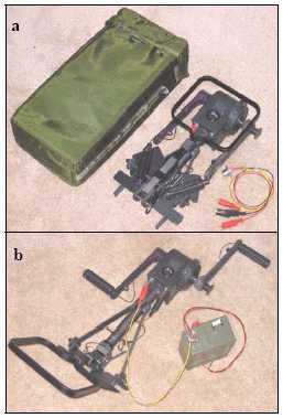
Figure 1. (a) The G-67B/G stowed configuration with carrying bag and battery cable. (b) Connected to BB-390 battery. The entire G-67B/G, which also includes a folding stand for anchoring the device, weighs 6.5 lbs and occupies a 16 x 8 x 4 inch volume when in its stowed configuration. The two crank arms on the device are 6.63 inches in length. As part of the OP-177/ U Power Supply Assembly, the unit is packaged with a solar panel and various adapters and cables. The G-67B/G is primarily used to charge 24-volt batteries.
2.2 System characterization tests for the G-67B/G In an October 1994 report (Allmon & Hopkins), ARL presented results of a series of tests that were conducted on the G-67B/G (and the 1C G-67) that compared the performance characteristics of the device when utilizing nine different rotor/stator configurations (including the configuration used during production). The performance of the configurations was determined through efficiency and acoustic noise testing. During efficiency testing, an electric motor was used to vary the cranking speed of the generator, and a torque arm was rigidly connected to the generator and instrumented with a strain-gauge bridge to provide indirect torque measurements. Output voltage and current measurements were made with the generator connected to loads of 10 and 20 ohms. Values for input power, output power, and ultimately the efficiency were then obtained for the unit using measured data and Equations 1 through 3 shown below,

where T is actual torque, (') is cranking speed, V is voltage, and I is current being supplied to the load. Using the rotor/stator onfiguration incorporated on production units, a peak efficiency of 62% was observed with the generator cranked at 95 rpm while connected to a 10-ohm load. Approximately 73 watts of electrical output power were measured in this operating condition, but a peak output of approximately 88 watts was obtained at 105 rpm. Under a 20-ohm load, a cranking speed of 95 rpm yielded a maximum efficiency of 63.5% and an output of approximately 47 watts. A maximum output of 52 watts was obtained at 105 rpm with the 20-ohm load. Acoustic noise measurements were recorded with a microphone directly in front of the generator head and 5 feet away for loads of 10 and 20 ohms. For the production rotor/stator configuration, sound pressure levels of 68.5 and 64.5 dBA were measured when operating the generator at 95 rpm under 10- and 20-ohm loads, respectively.
Another configuration consisting of a rotor with neodymium-iron-boron magnets and a different stator actually produced higher efficiencies and lower acoustic noise levels than the configuration used for production generators. Efficiencies as high as 69.5% were measured at 85 rpm with the 20-ohm load while sound pressure levels of 64 and 61.5 dBA were measured at 95 rpm under the two different loads. This developmental configuration likely would have been utilized for the generator had there been additional production runs. The voltage regulator circuit of the G-67B/G proved to be its performance-limiting factor throughout testing. The electronics of the particular generator that was tested regulated voltage at 31.4 VDC. As cranking speeds were increased such that the unregulated output voltage was greater than 31.4 VDC, the efficiency of the device went down. Excess electrical energy was dissipated as heat in the regulator circuit, and correspondingly, data was not measured at speeds that caused the G-67B/G to limit voltage in some cases. For the production rotor/stator configuration, 95 rpm was the maximum speed at which the unit could operate without limiting voltage during testing.
2.3 Design characteristics of Palm Power HTE-425
The Palm Power HTE-425, shown in Figures 2a and 2b, is a lightweight, hand-held, electrical power source that extracts mechanical energy from human hand cranking and converts it to electrical energy that is conditioned and controlled in order to safely charge portable batteries and small electronic devices at high rates. The device utilizes neodymium-iron-boron permanent magnet generator technology for its main power source and digital microprocessor-based electronic circuitry and power converter to control all generator functions. The converter can also be used to recognize and regulate auxiliary inputs such as solar panels. The user interacts with the Palm Power unit through an 8-character LED display that allows for monitoring of various system parameters such as cranking speed, current, voltage, power output, and cumulative energy in joules. When cranked or simply connected to a battery that has retained a small amount of charge, the device uses a relatively small amount of current to power the microprocessor and LED display. Controls are also provided such that the user can adjust the cranking resistance experienced during cranking. Greater power outputs are produced when the device is operated at faster speeds and higher crank drag torques. The output voltage of the device is dependent on the voltage of the battery being charged; it produces voltages near 8 VDC when charging an 8-volt battery and voltages near 12 VDC when charging a 12-volt battery.
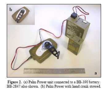
Figure 2. (a) Palm Power unit connected to a BB-390 battery. BB-2847 also shown. (b) Palm Power with hand crank stowed. The Palm Power unit weighs 1.3 lbs and occupies a 2 x 3.5 x 6 inch volume with its hand crank in the stowed configuration; the device has a 3.75-inch crank arm. Power outputs of 20+ watts are attainable with the unit, but the maximum output is dependent on the user's capabilities rather than device limitations.
2.3 System characterization tests for Palm Power
Test and evaluation efforts conducted on the Palm Power system during the past year were aimed at characterizing the system where specific requirements are not defined. The testing provided investigations of the battery charging capabilities and overall system performance of the units through a range of cranking speeds and input drag torques. Performance tests were designed to determine the overall efficiency of the units through various cranking speeds and torque settings, as well as the optimal cranking speeds and torques for operating at peak efficiency. In addition to basic power generation studies, other tests included a 50-hour endurance test, and a sound level test for aural nondetectability. Palm Power units were used to charge BB-390 and BB-2847 batteries throughout the tests.
The test setup utilized a 40-watt speed control motor and coupler to crank the removable unit at selectable speeds and torques. The CERDEC Power Generation Branch also modified the test stand to incorporate a 30 inch-pound in-line rotary torque sensor to measure the mechanical power input supplied by the motor. A noncontact RPM sensor (stroboscope) was consistently used to verify the cranking speed provided by the motor, and a data acquisition unit was used to obtain voltage & current data. Equations 1 through 3, as described previously, were used to calculate input power, output power, and efficiency. Ambient temperatures and internal temperatures of the Palm Power units were also logged during endurance testing.
Test results in Figure 3 indicated peak system efficiencies around 50% while Palm Power units were operated at mid-range torques and at a cranking speed of 120 rpm (2 revolutions per second). In this range of operating points, the device generates 8 to 11 watts of electrical power. The average male soldier can reasonably be expected to crank a Palm Power unit for about 5 minutes in this range.
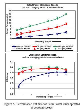
Figure 3. Performance test data for Palm Power units operated at constant speeds
A maximum output of 16 watts was measured when charging a BB-2847 at high torque and 120 rpm, but the output of the Palm Power unit was limited by the capabilities of the test stand rather than the device itself. Units tended to produce the same amount of electrical power regardless of whether a BB-390 or BB-2847 was charged but were more efficient at charging BB-2847 batteries, particularly at lower speeds. These same trends were also observed during tests in which the performance of the device was examined when maintaining constant power output by adjusting cranking speed at various crank drag torques. Power outputs of 3, 5, and 10 watts were investigated.
To characterize the endurance and reliability of the Palm Power system as a result of continued use, one of the units was subjected to 50 cumulative hours of operation during which batteries were charged at speeds of 90 or 120 rpm and low, medium, or high crank drag torques. Starting with discharged BB-390 and BB-2847 batteries, times were recorded at which a battery reached various states of charge (SOC) as per the battery's (SOC) indicator. As expected, charging occurred quickest during operation at higher torques and higher speed (120 rpm). In one particular test with a BB-2847, the battery reached 21% SOC within 28 minutes of accumulated cranking time and 83% after 127 minutes. Charging was also continued past 83% in this particular test scenario until the circuit opened after 156 minutes, implying a fully charged battery. No failures were experienced and no significant degradations in performance were observed as a result of the 50-hour endurance and reliability run. Throughout testing, two performance-limiting design issues were consistently encountered. Continuous operation at higher outputs (high torques & high cranking speeds) can result in an "Overtemp Alert" on the unit's LED display, but units have firmware logic that automatically reduces output at the onset of the alert to prevent damage to the unit. Additionally, units have an internally-set cutout threshold near 13.5 volts that limits the unit's effectiveness when charging higher voltage batteries such as the BB-390.
To examine acoustic noise levels produced during operation of Palm Power units, a sound level test for aural non-detectability test was conducted per MIL-STD- 1474C. One-third octave sound pressure levels were measured at multiple locations in a 2-meter radius around the operator while the device was cranked at high torque and high speed (120 rpm). Ambient noise level readings were recorded, and the test was also repeated with measurements being taken at a 10-meter radius around the operator.
Figure 4 shows field measurements that were obtained in relation to the noise limits associated with non-detectability distances of 100 and 200 meters as per MIL-STD-1474C. The relatively high sound pressure levels measured in the 2000 to 4000 Hz range dictate that the Palm Power HTE-425 is non-detectable when an observer is at a distance between 100 and 200 meters away (and beyond) in a "rural area" environment. While this data suggests that the device has potentially undesirable noise levels for operation in a tactical environment, it should be noted that audible noise requirements have not yet been established. (Moyers et al., 2004)
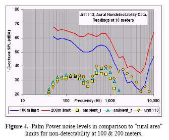
Figure 4. Palm Power noise levels in comparison to "rural area" limits for non-detectability at 100 & 200 meters. 5 3. SIDE-BY-SIDE COMPARISON
Results of system characterization tests obviously identified various strengths and weaknesses for both generators. This section aims to provide a direct comparison of the two technologies while identifying other significant differences that are not necessarily performance-based. Table 1 shown below outlines several of the relevant considerations surrounding the G- 67B/G and the Palm Power HTE-425 and is followed by brief, but more detailed synopses.
Table 1. Generator Characteristics Comparison Generator G-67B/G Palm Power HTE-425
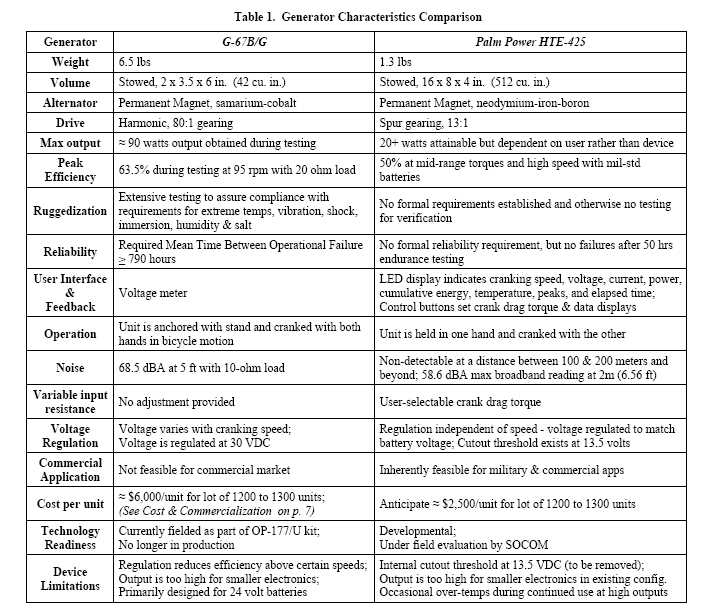
Weight & size: The relatively small size and weight of the Palm Power system is one of its stronger characteristics considering the relative amount of power it provides. It has a volume 1/12 the size of the G-67B/G and weighs 5 lbs less, but it produces lower power levels than the G-67B/G (depending on user effort). Figure 5 on the following page shows the relative sizes of the two generators in their stowed configurations. Electrical performance: During testing with 10- and 20- ohm loads, the G-67B/G operated at a peak efficiency of 63.5% and produced power outputs of nearly 90 watts. Palm Power was tested with military standard batteries and yielded maximum efficiencies of 50% at mid-range crank drag torques and high cranking speeds; higher levels of user input resulted in maximum power outputs above 20 watts. Further testing with more similar procedures and loads is required to arrive at a more representative comparison for the electrical performance of the two generators.
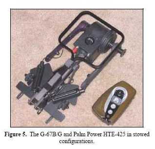
Figure 5. The G-67B/G and Palm Power HTE-425 in stowed configurations.
System Design: Both systems use permanent magnet alternator technology. Electronic circuitry converts the output of the alternator from AC to DC. The G-67B/G is essentially a "fixed" voltage device since it produces up to 30 VDC output regardless of the type of battery it is charging. The maximum speed at which the generator can be cranked is limited by the voltage regulation circuitry since faster cranking speeds produce greater unregulated output voltages. The Palm Power HTE-425, however, operates at a regulated output voltage that is dependent on the voltage of the battery to which it is connected. Output power for the unit is only limited by the user's capabilities. Additionally, the G-67B/G utilizes a Harmonic Drive with an 80:1 gear ratio for its mechanical drive mechanism while Palm Power has traditional spur gearing with a much smaller ratio giving lower gear stresses.
User Interface & Feedback: The Palm Power unit's user interface is another characteristic that distinguishes it from other energy harvesting technologies. When cranked or simply connected to a battery that has retained a small amount of charge, the device draws a small amount of power for its microprocessor and LED display.
The user is given feedback regarding various output performance parameters including cranking speed, voltage, current, power, and cumulative joules of energy produced. The user can manipulate which parameters are displayed using two control buttons on the unit. These buttons also allow the user to adjust the amount of resistance that is experienced while cranking; greater resistances produce higher power outputs at a given cranking speed. The G-67B/G has a voltage meter for user feedback, but it provides no means of adjusting input resistance or determining charging progress. The user feedback features of the two generators are shown below in Figures 6a and 6b.
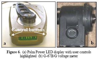
Figure 6. (a) Palm Power LED display with user controls highlighted (b) G-67B/G voltage meter Operation & Ergonomics: To operate the Palm Power HTE-425, the user holds the unit in one hand and cranks with the other. While much emphasis was placed on ergonomics during the development of the unit, some aspects of the design can be further refined to accommodate user comfort. For example, depending on the size of the operator's hand and the grip applied to the unit, it is possible to "scrape" one's fingertips with the crank. Ergonomics issues are currently being addressed in an on-going contract effort with High Tide Associates. Conversely, the G-67B/G has a two-handed cranking arrangement in which the device is anchored by the user sitting, kneeling, or standing on the folding stand while cranking the device in a bicycle fashion. Figures 7a and 7b show the G-67B/G configured for seated and standing operation, respectively, in comparison with the operational configuration for the Palm Power unit. Figure 7. (a) G-67B/G configured for seated operation. (b) G-67B/G configured for operation while standing. Palm Power operational configuration also shown.
Control buttons
Performance limitations: As stated previously, the output and efficiency of the G-67B/G are limited by its design. Efficiency is limited by the voltage regulation at higher cranking speeds, and the output voltage is also dependent on the speed at which the device is being cranked. In its basic configuration, the unit is primarily used to charge 24-volt rechargeable batteries such as the BB-390. Auxiliary circuitry would be required for the device to accommodate batteries of different voltages since its output is inherently too high for batteries such as the 8-volt BB-2847 and those of lesser voltage. Similarly, the Palm Power HTE-425 also has some limitations associated with voltage output. While the unit effectively charges BB-2847 batteries, its power output is currently too high to be compatible with lesser power requirements of smaller electronics. On the other end of the spectrum, the cutout threshold near 13.5 volts limits the unit's effectiveness at charging higher voltage batteries such as the BB-390. This issue was encountered throughout testing even though the pins for the connector to the battery were arranged such that the battery's two 12-volt cells could be charged in parallel. Both of these issues are being addressed under a new contract effort. Additionally, while the Palm Power units had the previously-mentioned issues with overheating, thermal management is not expected to be a performance limiting issue during normal operation where human strength and endurance are a factor.
Reliability: The G-67B/G is currently fielded and is subject to military specifications described in MIL-G- 49469(HD). In regards to reliability, the device is required to demonstrate a Mean Time Between Operational Mission Failure of no less than 790 hours. Reliability testing involves operating a generator for one hour at a time at a cranking speed of 68 rpm while connected to 15-ohm load followed by 1 hour of rest. This procedure is repeated until the generator has accumulated a total of 87 operating hours, and a sample of 10 generators is tested for reliability with this procedure. (US Dept. of Defense, 1991) The Palm Power unit is still a proof-of-concept, and in the absence of formal requirements, the 50-hour endurance test was conducted to investigate the reliability of the device. The device was used to charge BB-390 and BB-2847 batteries at different cranking speeds and crank drag torques. No failures were observed and the performance of the unit was not compromised as a result of the accumulated operational time. Ruggedization: As per MIL-G-49469(HD), the G- 67B/G was subjected to extensive product assurance testing. Units were required to meet operability and performance requirements at operating temperatures from -50ºF to 120ºF, after vibration and shock, after prolonged exposure to humid conditions, after immersion in water, and after exposure to salt atmospheres characteristic of coastal areas. (US Dept. of Defense, 1991) No formal requirements for ruggedization have been established for the Palm Power unit since it is still in developmental stages.
Cost & Commercial Application: The G-67B/G was developed by ARL for other Department of Defense agencies and was therefore never intended for the commercialization. The cost per unit was approximately $6,000, but this cost covered various aspects of the program including program management, production, production support, and design changes. (Personal communication with John Hopkins of ARL.) As part of a Dual Use Science & Technology program, Palm Power was inherently developed as a technology with both commercial and military applications. The materials and processes used were taken from the high-volume commercial electromagnetics market. Audible Noise Levels: Two entirely different procedures were used for noise testing of the G-67B/G and Palm Power HTE-425. The G-67B/G produced broadband sound pressure levels of 68.5 and 64.5 dBA at 5 feet from the head of the generator while the generator was cranked at 95 rpm and connected to 10- and 20-ohm loads, respectively.
For Palm Power, MIL-STD-1474 aural nondetectability testing involved measuring 1/3-octave noise sound pressure levels at multiple locations in a 2 meter (and also 10 meter) radius around the operator and device. Broadband measurements at 2 and 10 meters were also included in the data acquisition. The maximum broadband reading for Palm Power at 2 meters (6.56 ft) was 58.6 dBA while the unit was connected to a BB-2847 and cranked at 120 rpm with high crank drag torque. Further testing with more similar procedures and operating conditions is required to arrive at a more representative comparison of noise levels.
4. ON-GOING IMPROVEMENTS TO THE PALM POWER UNIT
Based on test findings and user feedback, SOCOM has provided additional program funding under a new contract in FY04 for the development of retrofit upgrades to existing Palm Power HTE-425 units. The upgrades will ultimately improve functionality and enhance operational capabilities by incorporating provisions such that the units are compatible with a wider range of electronic devices. Performance limitations associated with the internal cutout threshold will be addressed, and firmware and circuitry changes will be made to improve instrumentation for sensing voltage, cranking speed, and
current to provide more accurate feedback to the user. Units will also be modified to incorporate an energy buffer or energy storage device such that the units can accommodate electronics devices with small power consumption such as personal data assistants (PDA), cell phones, and global positioning system (GPS) receivers; Palm Power in its existing configuration likely produces too much power for these devices, even at lower output levels. Refinement of the ergonomics is also planned in an effort to further accommodate user comfort. Figure 8 shows various concepts that are being considered as ergonomic enhancements for the grip and crank.
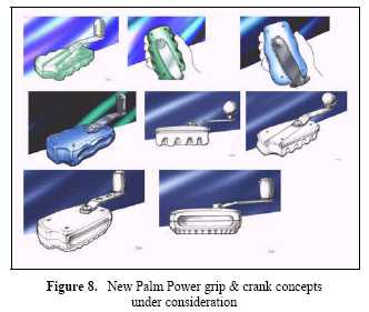
Figure 8. New Palm Power grip & crank concepts under consideration
Although it is not included under the current contract effort, improved sound attenuation will likely need to be addressed at some point for Palm Power, whether through system design modifications or improvements to the manufacturing and assembly process. Formal noise requirements have not been established, but low observability is a relevant consideration for this technology since the device is intended for use in dismounted Soldier missions. (Army CERDEC, 2004)
5. CONCLUSIONS
Based on user requirements and feedback during the early 1990's, the G-67B/G was primarily designed to recharge 24-volt batteries and provide power to radios and other electronic equipment with similar voltage requirements; the power output of the device makes it a feasible option for completely recharging a higher voltage/larger capacity battery in 1.5 to 2.5 hours. During the 10+ years since the G-67B/G was first produced, the equipment inventory and associated power requirements for outfitting dismounted Soldiers have changed. Department of Defense organizations such as SOCOM are opting for smaller, lighter equipment, and technological advancements in electronics and computers have resulted in devices that require smaller amounts and greater varieties of power to operate. Accordingly, Palm Power is being developed as a small, flexible, lightweight emergency power source that can be used to "top off" or restore a charge to larger capacity batteries while also providing power levels appropriate for completely charging smaller batteries such as those found in cell phones, PDAs, and other small electronics.
ACKNOWLEDGMENTS
The authors would like to thank John Hopkins of the Army Research Laboratory for loaning us a G-67B/G and providing information and test data on the device.
REFERENCES
Allmon, W.R. and J.W. Hopkins. October 1994: A Comparison of Performance Characteristics of Nine Rotor/Stator Configurations for the Hand-Cranked Generator, Army Research Laboratory Test Report, pp. 1-23.
U. S. Department of Defense. April 1991: Military Specification, Generator, Hand Cranked, G-67B/G, MIL-G-49469(HD), pp. 2-31.
Moyers, W.L., H.S. Coombe, and A. Hartman. 2004: Palm Power: Manually Cranked Battery Charger, Proceedings of the 41st Power Sources Conference, pp. 1-4.
U. S. Army RDECOM CERDEC. 2004: Test & Evaluation of the Palm Power Energy Harvesting System, pp. 1-25.
ADDITIONAL INFORMATION
To learn more about the Palm Power energy harvesting program, please contact the corporate and government program representatives shown below.
Weston Moyers or H. Scott Coombe
U.S. Army RDECOM CERDEC
weston.moyers@armypower.army.mil
scott.coombe@armypower.army.mil
Albert Hartman
High Tide Associates
ahartman @ieee.org
FEEDBACK!
Private Murphy's View
 On your desk?
 RETURN TO AES HOME PAGE